ULPNode RF Protocol
ULPNode RF Radio protocol was intended first time to be part of ULPNode library, but as soon as I tried to compile gateway code for other target as ESP8266/Particle/PI and others, some targets env compile all source folder file and as ULPNode library is intended for ATMega328 this was generating errors unless I start playing with #define everywhere.
I Also found not relevant that any gateway need the whole ULPNode library which is dedicated to node compilation only. That is why I decided to outsource RF Protocol to be able to compile easily on any target. I do not know if it’s the best way, but I find it very simple and working.
Please note that it’s preliminary documentation and may change in a near future
RF Protocol overview
The RF protocol is based on the excellent software stack RadioHead developed my Mike. Not only very well coded, it works fine and there are a lot of Hardware modules we can use with it such as RFM69 (my favorite one) or NRF24L01 .
The RF protocol definition is quite simple and dynamic, these mean that a Node (identified by a Node ID) can send any number of sensors data in the frame to a gateway (identified by a gateway ID). We could extend also the Network ID to separate different networks but for now it’s fixed by ULPNode RadioHead driver library.
A packet is just a suit of data bytes organized. I will not describe the low level (preamble, sync bytes, header, CRC) because it depends on hardware module used and it’s managed by RadioHead library. But as examples here how it works for RFM69 and NRF24L01
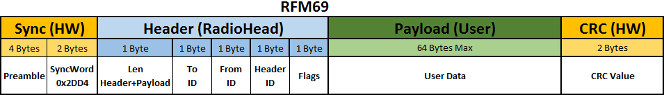
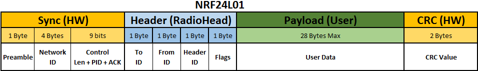
- Yellow cells are done by hardware module, RadioHead library has the ability to changes SyncWord, and Network ID
- Blue cells are managed by RadioHead library, ULPNode has the ability to changes From and To ID and use some user Flags
- Green cells are managed by ULPNode and user sketch
What you’re mainly interesting in, is the payload, the bytes you need to send/receive all other is managed by RadioHead library and header is managed by ULPNode library and Gateway
And finally here is the protocol definition
RF Protocol definition
Node to Gateway
When a Node is sending data to the gateway, it set the type of transmission needed (this internally set headers flags), what can be done with ULPNode are :
- Send without control : data is sent, no reception control is done, so the packet can be lost (distance, interference, collision, …). RadioHead call this unreliable transmission.
- Send with ACK : data is sent and wait for gateway to acknowledge sent packet. If no ACK is received, Node try again to send the packer (2 more times), this means that it tries a total of 3 send before considering a failed transmission. RadioHead call this reliable transmission.
- Send with Request response : data is sent and wait for gateway to send back a response (example is a advanced ping packet for example). If no response is received, Node try again to send the packet (2 more time), this means that it tries a total of 3 send before considering a failed transmission. This is done in ULPNode library since RadioHead does not handle this kind of transmission.
One point to note is that you need to instance the RadioHead and tell it what kind of transmission you want to use, reliable or not reliable. This means that a non reliable node can’t talk to reliable node and this versa. And I do not wanted this, I needed a node to be able to talk reliable (sensitive and critical data) AND not reliable (basic, not so much important data) to the same Gateway. This is why I used basic driver and datagram transmission of RadioHead and implemented Reliable a higher level and standard version in ULPNode library (mainly inspired from reliable datagram of RadioHead). So ULPNode can do both, great !
The two sending methods are provided by ULPNode library you don’t need to manage this. You just need to select the one you want to use when you send a packet. ULPNode will take care of retries and will just tell you if it succeed.
ULPNode can build mainly (for now) 2 types of payloads, a command action, or sensor data as follow. the type is determined by the 1st payload byte and it can be a command code or succession of sensor data small structures code.
Payload Command action (always 1st byte of payload)
The payload control code indicate what we’re sending/receiving, the values definition are following
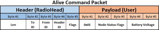
Code 0x01 ALIVE
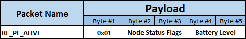
Alive packet is a small packet to indicate we’re alive, we send node status flags and node battery voltage in mV
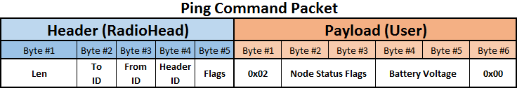
Code 0x02 PING
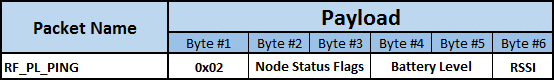
Ping packet is a small packet to verify Gateway communications, we send node status flags and node battery voltage in mV, we set RSSI to 0 it will be filled in Gateway response
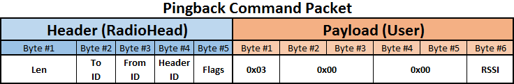
Code 0x03 PING BACK
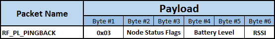
Ping Back packet is the response to ping packed and issued by the Gateway as a response to node. Same data structure are returned, Status and Battery level are set to 0 and RSSI is filled. The RSSI contains at which RSSI level the Geteway received the Ping packet. Could be used to determine auto RF TX power level to use. Decrease if node near Gateway (High RSSI), Increase if it’s far (low RSSI).
Code 0x04 Config
Preliminary : need to be implemented, we should be able to Send Node configuration from Gateway Web interface
Code 0x05 OTA
Preliminary : need to be implemented, we should be able to do Firmware update from Gateway Web interface
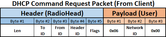
Code 0x06 DHCP Request
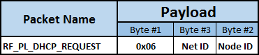
DHCP Request can be asked by the Node to request a Free Node ID to the Gateway. Unconfigured node will have a defined and fixed Node ID. Node ID should be 0 on request, and will be filled in Offer response. Net ID is not yet used.
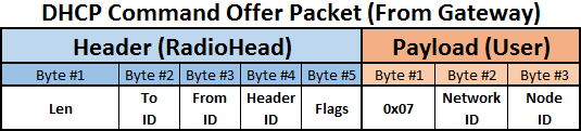
Code 0x07 DHCP Offer
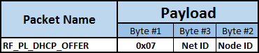
DHCP Offer is send the node ID attributed by the gateway if there one free, else 0. Net ID is not yet used.
Payload Sensor Data (1st byte of payload and so on)
When I started to code protocol I began with payload definition for each type of full frame sent and I quickly managed too much frame type because you can add so much and different sensors on ULPNode that it became a nightmare to manage. I needed smart things.
That was time of dynamic payloads, we’ll need to send as much data as we want without managing fixed frame payloads. The idea was to create small structures for each sensor type (temps, battery, lux, …) and then add the one we need to the payload, in whatever order we want. We just need to indicate what type of data it is, we can add new without touching existing sensors, fine !
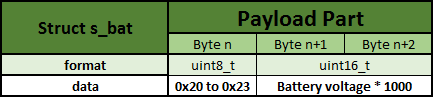
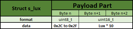
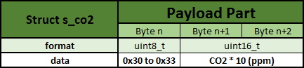
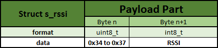
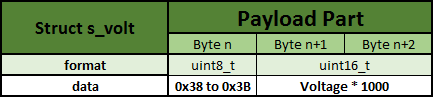
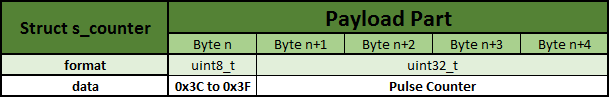
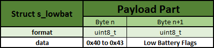
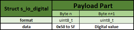
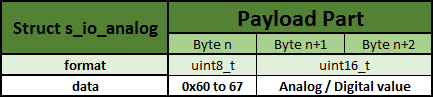
To achieve this here are the structure defined for data, each structure contains at least one byte to identify data and one ore more depending on data type. Then these structures are put in the payload one following other, and the Gateway will recognize data type and will be able to decode them. Each structure can have up to 4 values in case of multiple sensors of same type
Code 0x20 to 0x23 Battery Level
Code 0x24 to 0x27 Temperature

Code 0x28 to 0x2B Humidity

Code 0x2C to 0x2F Luminosity
Code 0x30 to 0x33 CO2
Code 0x34 to 0x37 RSSI Level
Code 0x38 to 0x3B Voltage Level
Code 0x3C to 0x3F Counter
Code 0x40 to 0x43 Low Battery Flag
Code 0x50 to 0x5F Digital IO pin value
Code 0x60 to 0x67 Analog IO pin value
Of course this list is just a beginning it will be extented with future uses
RF Protocol Payload examples
I know this is a lot of information and and 1st reading it could seem complicated, but to be make things simple I’ve put some payloads examples relative to what I’ve just talked about.
Command Payload
I’m alive 😉
Ping request
Response to ping
Request new Node ID
Node ID offered
Sensor Data Payload
Sensor Data sent by ULPNode example sketch Wake_Transmit_Sensor.ino, as you can see, user payload is a succession of sensor structure data, we can add 1 or remove one, no problem.
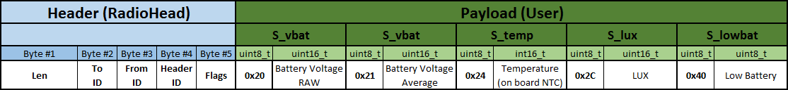
Resulting in the Gateway of the following JSON output (as example) from serial (node id is 13)
{id:13,rssi:-85,bat:1.222,bat1:1.219,temp:26.2,lux:2.1,lowbat:0}
This one is sent by ULPNode example sketch Wake_Transmit_Sensor_si7021.ino, as you can see, SI7021 data sensor has been added to the previous example (click to zoom). The first s_temp (on board NTC sensor) has code 0x24 and the optionnal 2nd one from SI7021 I2C sensor has code 0x25

Resulting in the Gateway of the following JSON output (as example) from serial (node id is 12)
{id:12,rssi:-71,bat:1.078,bat1:1.077,temp:26,lux:0,lowbat:0,temp1:26.23,hum:62}
Or if you have enabled a display on the Gateway, you can see something like that

ULPNode Gateway With Custom Moteino
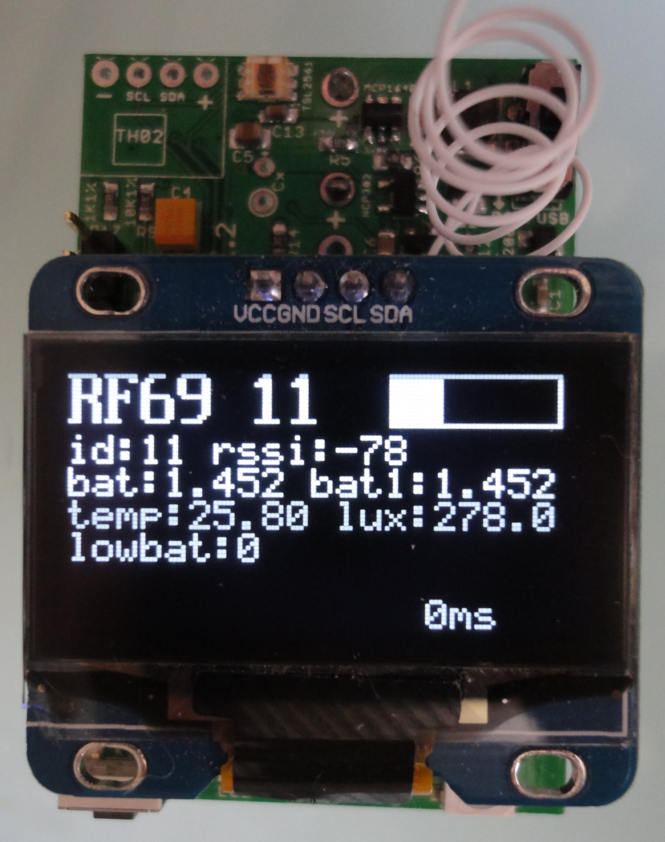
ULPNode Gateway done with another ULPNode
Source code usage
The source code for ULPNode RF protocol is available as separate code on github. It’s not a C++ library or any other executable program, just header files and a cpp file so like this, whatever Gateway you want to compile for, you just need to copy this folder on your compilation project
If your Gateway is Arduino based, you just need to put ULPNode_RF_Protocol folder into your Arduino Libraries folder as any other library.
References
- ULPNode RF Protocol sources code
- All ULPNode related articles on my blog
- My Github repository