This post describe the procedure used to verify that ArduiPi board is working correctly.
Edit 03/17/2014 : Modified for testing ArduiPi Rev 1.1 board
What do you need ?
- A Raspberry Pi Rev 2 with Raspbian, I recommand the Wheezy version (Revision 2 board is mandatory to test the new GPIO available on the Raspberry board. If you have a Revision 1 the ArduiPi board will not be correctly tested for the new GPIO
- Raspberry Pi test scripts for ArduiPi
- A Seeedstudio I2C Grove 96×96 OLED display
- A ArduiPi Board with Arduino flashed with test firmware
- A ArduiPi test board with pogo pins to get onto the ArduiPi pads (or other methods if you solder connectors onto your ArduiPi board)
- A external power to power the ArduiPi board (9 to 12V is fine)
Assumptions
- You must have dev tool installed onto your Raspberry Pi for compilation and a updated Wheezy distribution is preferable.
- You can connect to the Raspberry Pi with SSH or launch a root terminal directly on the Pi connected to a screen with keyboard
- Electronic and IT skills are preferable in case of problem
Configure ArduiPi board
- Set the switch named PI_VCC_EXT to the EXT position to tell the board you are using external Power
- Set the switch named 3V3_VDD_5V to the 5V position to tell the board we are going to work with 5V power
- Flash Arduino Test Firmware onto the Arduino of ArduiPi board (using FTDI cable and connector is perfect for this). The ArduiPi board have the correct FTDI connector on the board. The test program firmware for Arduino is located on the ArduiPi github repository. More precisely here.
Installing the test shield
- Plug the ArduiPi test board onto ArduiPi board (with Raspberry powered off)
- Plug the OLED display in Grove connector I2C_OLED of the test board
Take Care, the ArduiPi 1st prototype and test board have line SCL and SDA reversed (only on I2C Grove connector) so you need to manually invert SDA and SCL on your Grove cable- If you want to program the Arduino again you will need to remove the test board because the test board connect Pi Uart to Arduino Serial and this conflict with Arduino flash (This is corrected on latest test board PCB with jumpers)
- Power on Raspberry Pi
- Plug external power onto ArduiPi board (Led state are fancy, don’t worry this is okay)
What should happen ?
- Led 2 to 9 of ArduiPi test board
- should blink one after one in a loop (Arduino is alive !!!)
- OLED display should display test passed state of differents features as follow :
- 1-Wire communications between Arduino and I2C controller
- Analog input values on ArduiPi board
- I2C communications between Arduino and Raspberry PI
- SPI communications between Arduino and Raspberry PI
- Serial communications between Arduino and Raspberry PI
Of course, until action is done on Raspberry PI, 3 of theese tests will fail, the tests of communication between Arduino and Raspberry PI (I2C, SPI and Serial) should display — instead of OK
Here below a screen shot of what should be displayed
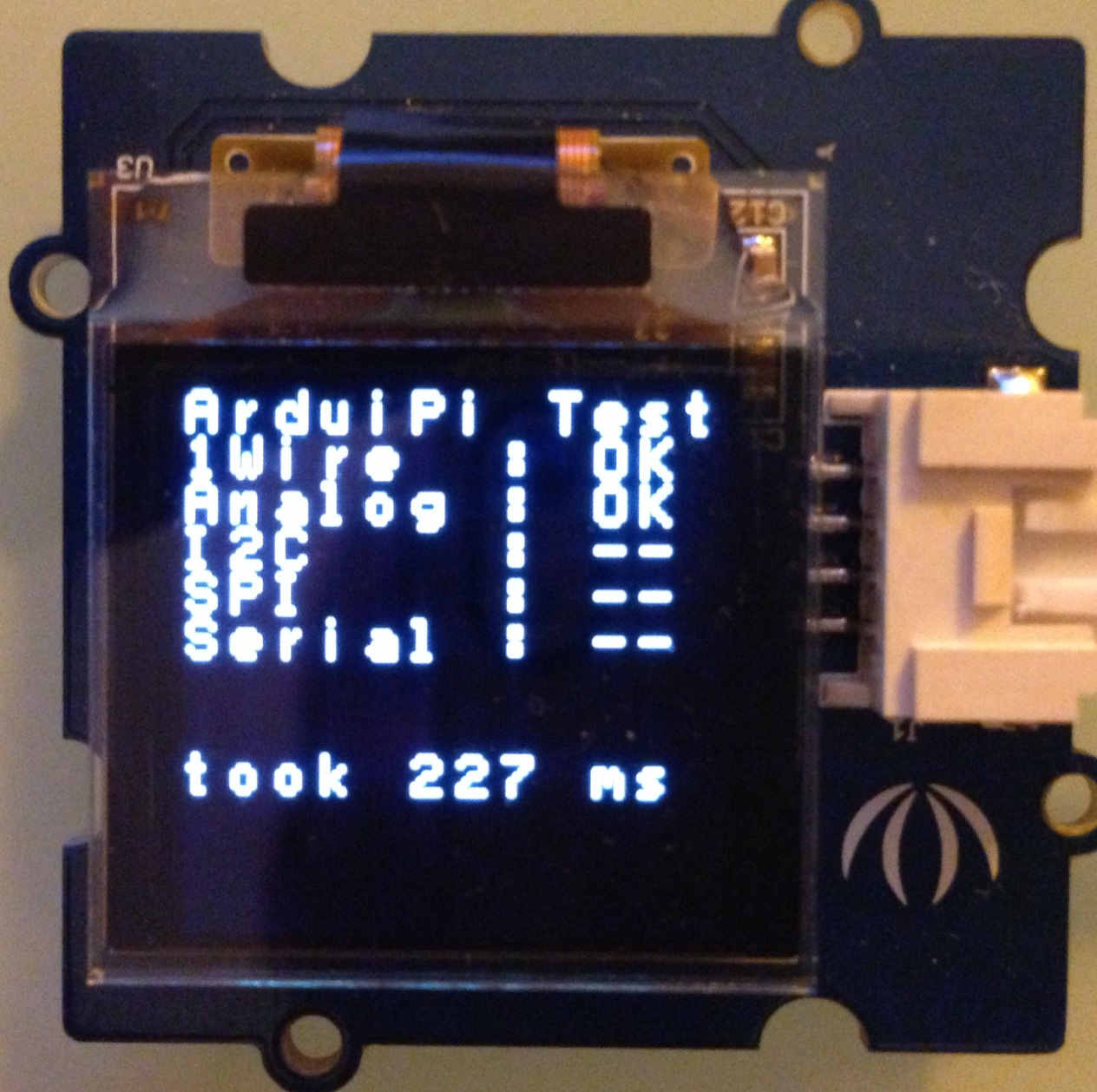
ArduiPi-test-nok
Ok done, now go to Raspberry Pi
I am connecting to Pi with ssh, once you’ll on the Pi issue the following commands to be able to compile. Because you will need the compiler and some others tools :
sudo apt-get install build-essential git-core libi2c-dev i2c-tools
Free up the serial port used by the Linux console
Please check the post I already wrote for enabling the serial port on Raspberry Pi, follow the procedure.
Install I2C and SPI modules on Pi
By default I2C and SPI modules are disabled onto Raspian Wheezy version. You need to enable the kernel modules to be able to use SPI and I2C. to do so, edit the file raspi-blacklist.conf do disable the blacklist module
sudo nano /etc/modprobe.d/raspi-blacklist.conf
Then comment the two lines that are blacklisting the modules adding # before, this should be something like that :
#blacklist spi-bcm2708
#blacklist i2c-bcm2708
Verify that the file /etc/modules contains the following lines and add them if it is not the case to autoload these modules at bootup.
spi-bcm2708
i2c-bcm2708
i2c-dev
now reboot your Pi
After reboot check that the modules are loaded, you should see both i2c_bcm* and spi_bcm*.
pi@pi02:~# sudo lsmod | grep bcm
snd_bcm2835            16304  0
snd_pcm                77560  1 snd_bcm2835
snd                    58447  5 snd_bcm2835,snd_timer,snd_pcm,snd_seq,snd_seq_device
i2c_bcm2708             3759  0
spi_bcm2708             4816  0
pi@pi02:~#
Installing WiringPi library and tools
To drive the Raspberry PI I/O ports I decided to use the small and pretty cool library named WiringPi from here. You need to install this library on the Raspberry, follow this tutorial for doing that. Thank to Gordon for this excellent job.
Installing ArduiPi tools from GitHub repo
The ArduiPi program is the program that permit communications between the Raspberry Pi and Arduino. It can do I2C/SPI and Serial communication according the ArduiPi protocol defined for this project.
Download ArduiPi tools suite suite from the ArduiPi github repository by cloning the repository.
git clone https://github.com/hallard/arduipi/
The ArduiPi program is located into folder raspberry/ardupi. To build it, Issue a :
cd arduipi/raspberry/arduipi
make
sudo make install
If all went well, the aruipi program has been installed into /usr/local/bin folder. Check this out using a :
pi@pi02:~/github/arduipi/raspberry/arduipi# arduipi -h
arduipi
Usage is: arduipi [options] [protocol] [mode] [-d device] [-a address] [-t data]
  --<D>evice   : device name, i2c or spi
  --<a>ddress  : i2c device address (default 0x2A)
  --<d>data    : data to send
protocol is:
  --<I>2c      : set protocol to i2c (default)
  --<S>pi      : set protocol to spi
mode is:
  --<s>et value: set value (byte or word type determined by data size)
  --<g>etbyte  : get byte value
  --<G>getword : get word value
  --<q>uick    : i2c quick check device
  --ac<k>      : i2c check if device sent ack
Options are:
  --ma<x>speed : max spi speed (in KHz)
  --dela<y>    : spi delay (usec)
  --<b>its     : spi bits per word
  --<l>oop     : spi loopback
  --cp<H>a     : spi clock phase
  --cp<O>l     : spi clock polarity
  --<L>sb      : spi least significant bit first
  --<C>s-high  : spi chip select active high
  --<3>wire    : spi SI/SO signals shared
  --<N>o-cs    : spi no chip select
  --<R>eady    : spi Ready
  --<v>erbose  : speak more to user
  --he<X>      : show return values in hexadecimal format
  --<V>ersion  : show program version and Raspberry Pi revision
  --<h>elp
<?> indicates the equivalent short option.
    long options always in lowercase
Short options are prefixed by "-" instead of by "--".
Once done we could check that Arduino is seen on i2c bus and other devices issuing a
i2cdetect -y 1
you should have the following result (use i2cdetect -y 0 if your Pi is revision 1)
     0  1  2  3  4  5  6  7  8  9  a  b  c  d  e  f
00:          -- -- -- -- -- -- -- -- -- -- -- -- --
10: -- -- -- -- -- -- -- -- 18 -- -- -- -- -- -- --
20: -- -- -- -- -- -- -- -- -- -- 2a -- -- -- -- --
30: -- -- -- -- -- -- -- -- -- -- -- -- 3c -- -- --
40: -- -- -- -- -- -- -- -- -- -- -- -- -- -- -- --
50: -- -- -- -- -- -- -- -- -- -- -- -- -- -- -- --
60: -- -- -- -- -- -- -- -- -- -- -- -- -- -- -- --
70: -- -- -- -- -- -- -- --
Raspberry saw 3 devices :
- 18 is DS2482 1-Wire controller
- 2a is the Arduino of ArduiPi board
- 3c is the Grove OLED display
Ok all seems fine, now deep test the ArduiPi board
Goto the folder containing the test_board shell script that need to be launched on the Raspberry Pi.
cd ../test_board/
This script use WiringPi command so remember that this need to be installed onto the Raspberry Pi as indicated above so as the ArduiPi executable.
To be sure the first time, set the script to executable issuing a :
chmod ugo+x test_board.sh
Now you can launch the script from Raspberry by :
sudo ./test_board.sh
What should happen ?
- Script will ask you to press POWER-PI switch button (ArduiPi board V1.1 only) to start test.
- Then script will test autoreset feature by issuing a reset to Arduino using GPIO 18 (ArduiPi V1.1)
- Led D13 should blink 2 times indicating that Arduino reset has been done (ArduiPi V1.1)

ArduiPi-test-ok
- I2C Communications on OLED should
- pass from — to OK
- SPI Communications on OLED should
- pass from — to OK
- Serial Communications on OLED should
- pass from — to OK
- Raspberry Leds (17 and 18 are disabled on ArduiPi board >= V1.1 because GPIO are used for Power PI and Auto-Reset features)
- Leds CE1, 4,
17, 18, 21, 22, 23, 24, 25, 28, 29, 30, 31 should all be off
- Leds CE1, 4,
- then
- Leds CE1, 4,
17, 18, 21, 22, 23, 24, 25, 28, 29, 30, 31 should all be on
- Leds CE1, 4,
- then
- Leds CE1, 4,
17, 18, 21, 22, 23, 24, 25, 28, 29, 30, 31 should all be off
- Leds CE1, 4,
- then
- Leds CE1, 4,
17, 18, 21, 22, 23, 24, 25, 28, 29, 30, 31 should now cycle
- Leds CE1, 4,
- then script will end
You must also test the 2 free pins by pressing the tactile switches on the test board. SW1 should lit LEDFREE1 and SW2 LEDFREE2
If all these steps worked, ArduiPi board is working fine, and I hope you will have fun with it.
Charles