Use RFM12B, RFM69CW, RFM69W or RFM69HW, Micro SD or Flash EEP with NRF24L01 connector of ArduiPi board (or other)
Updated 2014 September
I created 3 other small boards, V1.2 without SD but very small, the V1.2 SMD ultra small (version is approx the same size as the module itself) and another one for RFM69HW and RFM69W.
Version 1.2 (RFM12B, RFM69CW) NO SD (github)
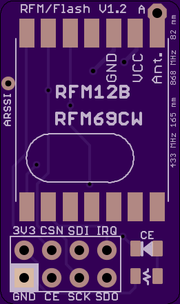
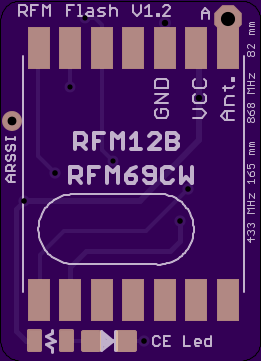
Version 1.2 SMD (RFM12B, RFM69CW) NO SD (github)
Version for RFM69 (RFM69W, RFM69HW) with SD (github)
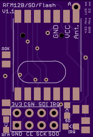
Old Version 1.1 (RFM12B, RFM69CW) With SD (github)

Original Post
Here is the new board module, how to use RFM12B and MicroSD/Flash EEP from NRF24L01 connector. You can use this breakout board directly onto a ArduiPi board.
NRF24 to RFM12B/SD board V1.1
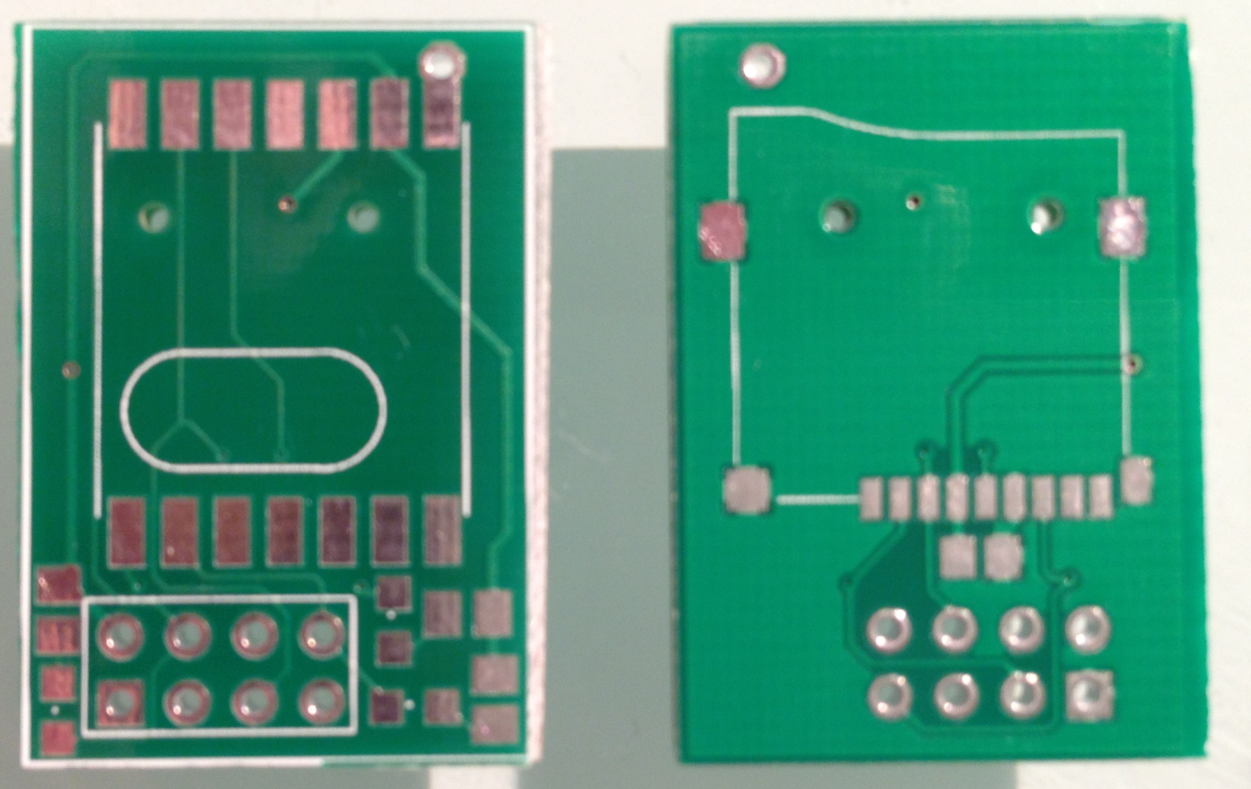
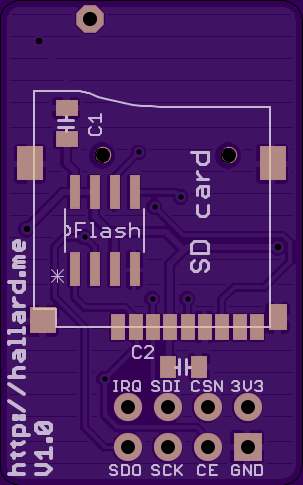
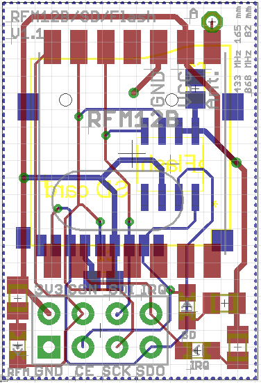
RFM12B breakout board PCB V1.0 with silk error, missing some text !
History
In a previous post when I was testing maximum distance transmision of the NRF24L01 modules, I was surprised of the low range, 30/50 meters in outside clean area.
It was time to do something, of course I keep in mind testing the new NRF24 modules with PA+NLA but I also wanted to test some other technologies. It is time to take a look onto RFM12B modules, very popular on Internet. They use 433MHz, 868MHz or 915MHz frequency, depending on your country, but you can choose your frequency. The goal is to be able to use the new modules without a redesign already done for ArduiPi board that contains the two NRF24L01 connectors (one for Pi, and one for Arduino).
So I will be using, the NRF24L01 existing connector. And we are lucky, the NRF24L01 need SPI pins but also 2 more I/O pins that are for CE and IRQ. RFM12B module also use IRQ pin, so we will use the same and it leave us another I/O pin. Hummm, what can we do with a SPI bus, and a free I/O ? Just adding new SPI device that will be driven by the free I/O pin as Chip Select for example ? What about something to store data ?
Here we go, I will add Micro SD header and a JEDEC SPI flash memory on this board, letting you the choose to use the Micro SD card or the flash (can’t use both, remember, we have only one I/O to drive the SPI device), so you can choose to solder the SD card or the flash memory.
I also added three optionnals LEDs so see signal IRQ, activity on RFM12B and activity on SD/Flash. I do not know why, but I love LEDs and I like to see what is going on 😉
Design
I already have the board (V1.0) in my hands, but I made a error in panelizing other PCB so there is no silk (the text you see on PCB) on the boards, but they are working fine. Also In V1.0 there is no place for the SPI flash but I added it onto V1.1 board (and corrected silk error).
Pictures
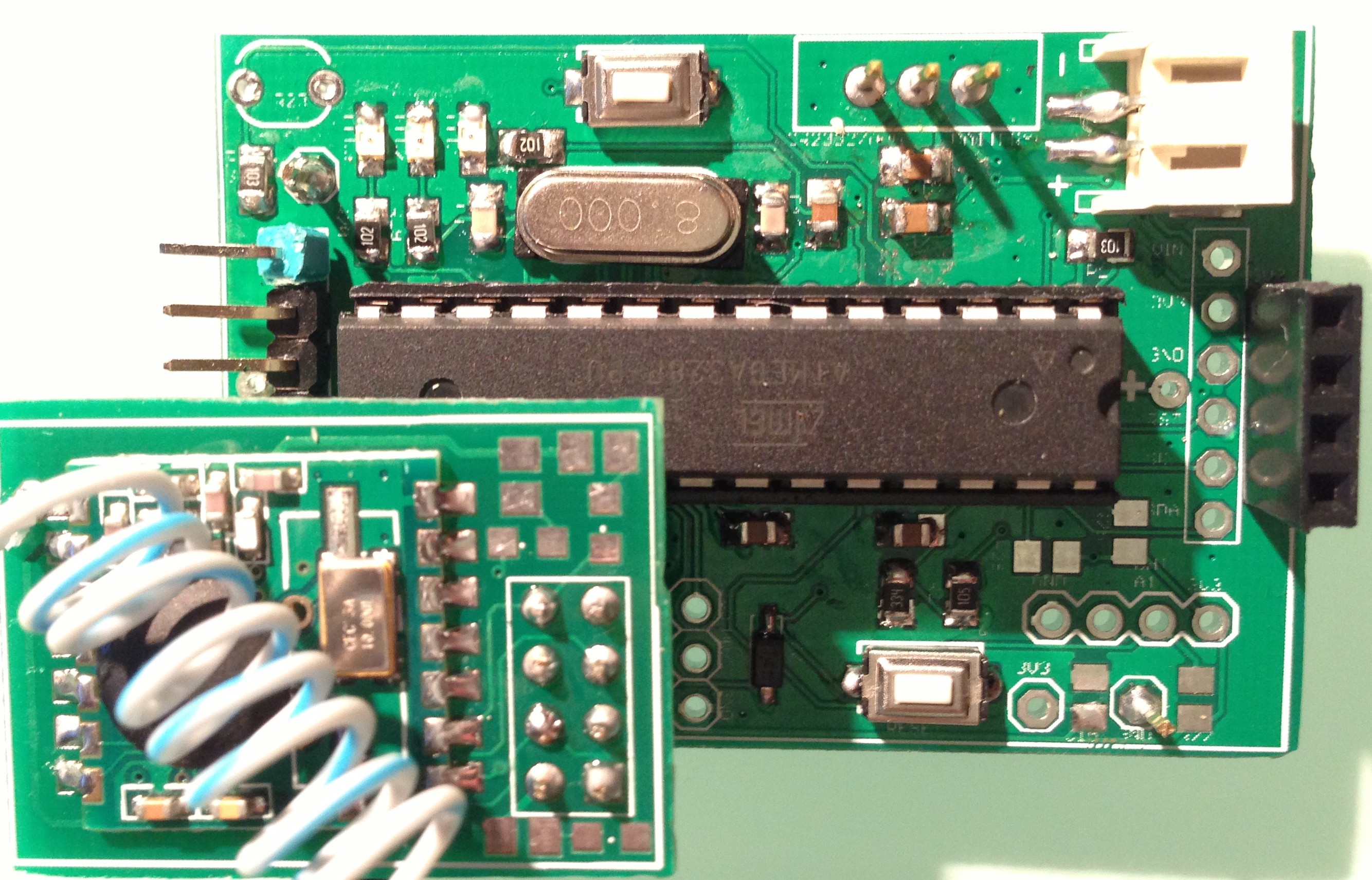
RFM12B breakout board on ArduiNode
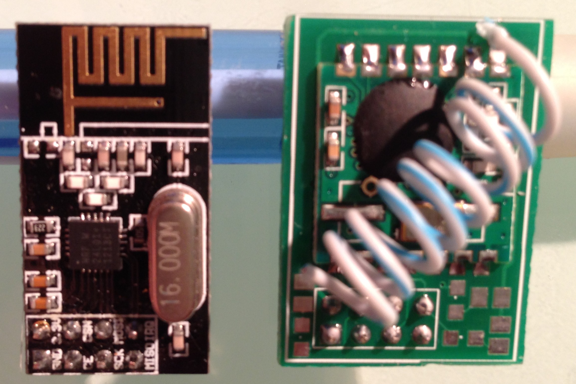
RFM12B- vs NRF24L01 differences
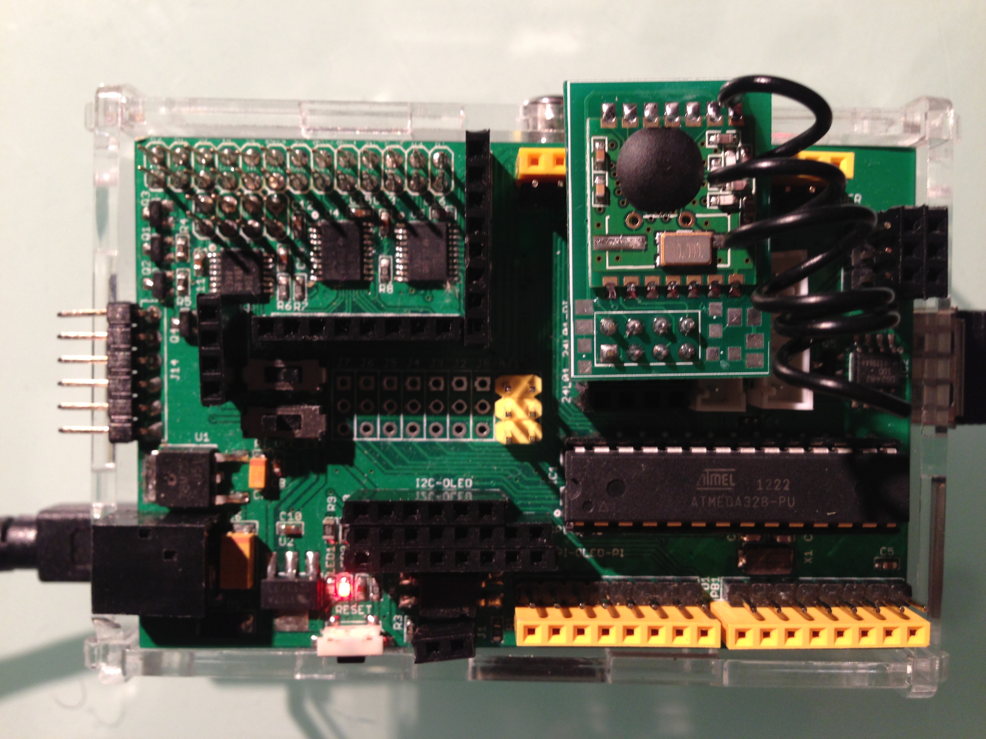
RFM12B breakout board on ArduiPi
All files, schematics, and are located on my Github, and I will post demo code soon