After several articles and some intensive tests with ULPNode, it’s now time to explain how the low power engine has been built. Even if you can find plenty of Arduino clone node, when it’s time to power them with battery and using power optimization, I never succeeded to find one fitting my needs. Today I can say that ULPNode is the less consuming power nodes ever built. It works also from several power sources (AA, AAA, Cell coin, ….). May be some are existing but not released to public so I’m not aware. If you find one do not hesitate to tell me, I’m always curious to see how to achieve same things with other methods.
This article refers to several ones already written. That is why I will not be going into deep details on some points already discussed. If you want to have a whole vision of this project and a smoothly reading of this post, please take some time reading the previous following articles for detailed explanations on other points.
- Introduction of ULPNode
- Low Power Bootloader 1 and 2 for ULPNode
- ULPNode first prototypes status
How low can I go ?
Arduino boards are based on ATMel chip, the most commonly used one is the ATMega328p. Note that the last letter “p” is very important because it indicate “PicoPower, and this mean that it is the most dedicated for Low Power operations. Reading the datasheet this chip can work starting 1.8V wich it’s very suitable in our case. It consumption in total idle mode can be as low as 100nA (see datasheet section 29.2.8 ATmega328P DC Characteristics). As the node are doing most of their time in this idle mode, this is allowing us to run them at a really low consumption.
Conception
That said, to achieve this low power mode, we need to conform to the datasheet. A good advice is always read the datasheet on the point you need details, if something goes wrong, read back the datasheet, and remember, try to understand the author point of view, do not make any assumption on how you think you understand information written. the following cases are the one I used when I created ULPNode.
- In our case, we need to have the board not running at speed higher than 4MHz to be able to let it working until limit of 1.8V. So the default cruising speed of ULPNode need to be 4MHz, it will always work (we’ll see later how to increase this on demand).
- Lot of sensors or devices need to be powered with 3.3V, so we need to be able to get power to 3.3V on demand, for this, one way to do, using a DC/DC booster. This also mean that we can have 3.3V power when we decide and we need it.
- Ideally, since the consumption in idle mode of CPU is approx to 100nA, a good thinking would be to charge a capacitor to 3.3V before going into low power mode and then disconnect the main power from the CPU and sensors until the capacitor discharge reach about 2V. then we just need to charge back the capacitor to 3.3V and disconnect again, and so on. To achieve this, we need also a non conventional booster, this one should have a feature that lot of them do not have. This feature is called “true output disconnect”, that means that when not activated the input is not bypassed (lot of them do this) but instead it’s disconnected from the output. So every devices (CPU, Sensors, ..) located after the output of the booster does not draw any current on the battery in this mode. The only battery drawing is the Booster quiescent current in idle mode.
- So we need a voltage supervisor controller. Of course it may be technically possible to use the Arduino chip to manage and check discharge with ADC comparator and interrupt and then charge back. As I do not want that the software can interact and potentially break the powering engine, I decided to keep this to be done by hardware, it’s safe and user code don’t need to worry about that, and it will work even if there is a code bug. I’m sure this decision will remove some pain and headaches.
- But , even if low powering engine supervisor is done by hardware we need to be able to activate the booster on demand by software when we need it.
- Last but not least, of course all sensors and consuming devices need to be disconnected for low power consumption and activated only when we need them. This part will be done by software activating or deactivating sensors powering.
Functional diagram
Ok, now let’s put all of this into the shaker and here below the functional diagram of ULPNode power engine.
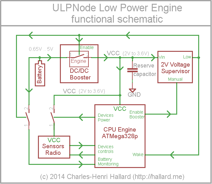
ULPNode Functional Diagram
How does this all works ?
As previously said, the booster as a nice feature called “true output disconnect”, this is acting like a switch, when the booster is enabled, the input voltage is stepped up to 3.6V (3.6V because I wanted the on-board RGB led to work correctly, datasheet says 3.5V) and most sensors works until 3.6V. thus this will give some extra time during the voltage decrease to 2V.
Once started, VCC line will bring to 3.6V until the booster is disabled. During this time you can do anything you want even speed up the processor to 8MHz (at 3.6V we can go to 8MHz). You can power the sensors, the radio module, whatever you like.
Once your job’s done (measure, radio send, ..) , you can enter to Low Power mode, for this, you must disable all sensors and CPU peripherals, then you can disable the booster and go into sleep mode.
Once in deep sleep mode, the supervisor will constantly check its voltage (VCC line) if above 2V. If it is above 2V, nothing happens, the low power consumption of the CPU will bring down very slowly VCC line trough the reserve capacitor. As soon as the voltage supervisor detect voltage under 2V (on my prototypes it is happening after approx 100 seconds), supervisor output becomes active and three things are happening :
- The booster is being enabled for about 30 ms (it is the reset pulse time of the supervisor) and the reserve capacitor is being charged to 3.6V.
- The battery monitoring is enabled.
- The third event is optional, but if you enabled the wake interrupt in the CPU, the CPU is waked and let you do the stuff you want to do (power on the sensors, reading them, sending measure with radio module, ..) Once done, you can go back to sleep after disabling the sensors and the booster. If you want to save more power and for example you don’t need to send data on every wake, you just need to have a counter variable in you loop and decide for example to read and send data only each “n” wake. In this case the wake will be very short in term of timing when doing nothing except increment the counter and testing it. Remember that the consumption is at the top when sending data through radio module (45 mA for RFM69 radio module) so just do it only when needed.
Why the third event is optional ? well, imagine you want to do a pulse counter (which is slightly different for example than sending data every 5 minutes for temperature or things like that). In this case you let the hardware doing the reserve capacitor recharge (so you won’t be waked on this event happening when VCC goes below 2V). ULPNode will work in this case in a mode I could call “free running mode”. You have nothing to manage except deciding and configuring before going to sleep which external event will wake you.
So if you program another I/O pin (the pulse counter) as interrupt. Then you will be waked each time this interrupt occurs. If pulse happens slowly, CPU could stay in sleep mode for a very long time (min, hour, day, month, …). Of course when waked by other IRQ (pulse counter), don’t forget to enable the and activate the booster as soon as you’ve been waked, this rule is always true. Even if voltage supervisor enable it for 30 ms, it does not hurt to confirm and force the booster until you finish what’s need to be done.
Bringing all of this to life
After these theoretical words, let’s go in the battle field, I’ve implemented a small sketch illustrating this all. The CPU is waked each time the voltage detector assert a “Wake” (VCC going below 2V). Then I power the sensors and the RF module, send a radio frame other the air to the gateway, wait for ACK from the GW and blink the on-board RGB led in green if ACK received else in red. Then going back to sleep. This event is happening every 100 seconds (each hardware wake).
Since 100 second is very long to do a scope capture, I’ve put a resistor between VCC and GND to force consumption during sleep mode, in this case, wake is happening approx every 1.2 second. It’s just to be able to capture a quick sequence on my scope. And here the result below :
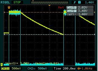
ULPNode Low Power capture graphs
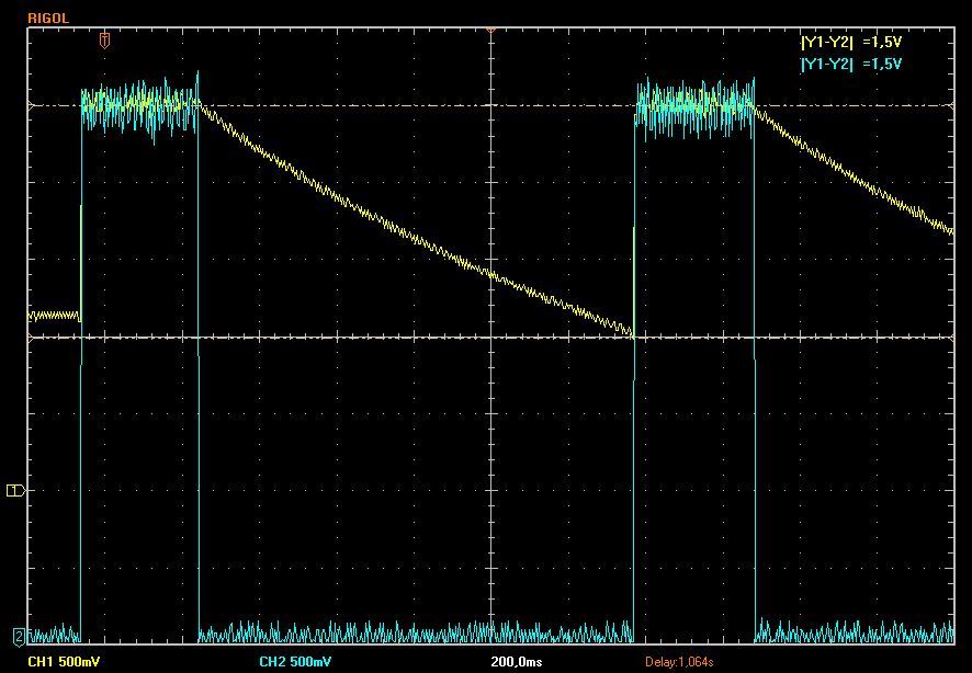
ULPNode Low Power capture graphs
On both images, the blue line is grabbed from “Enable Booster” signal (output of the voltage supervisor) and the yellow one is VCC, the master power voltage present on reserve capacitor and booster output when activated.
As you can see on the 1st image, the wake duration is about 300 ms (blue pulse) doing all the stuff I said before, then the CPU is set to sleep mode disabling the booster. Once booster disabled, CPU engine is free running mode, this means consume nothing on the battery because it is powered trough the reserve capacitor. VCC start going to decrease until it reach 2V, then supervisor activate back the booster and so on…..
You can also notice that when as long as the booster is activated, VCC stays stable approx to 3.5V.
Components Involved
ULPNode mains components used for all of this are a Microchip DC/DC booster MCP1640 the model is PWM/PFM with true output disconnect options. The voltage supervisor is a NCP302LSN20T1 the model with threshold detection at 2V.
Of course there are passive components all around for feedback, adapting/inverting signals and doing other things. And as a bonus, when booster is enabled, it enable the battery monitoring, this permit to know the battery level without drawing current from it when in sleep mode.
Next steps
I’m currently merging all code into a library to let you use ULPNode features without worrying a lot and using simple API. The sample code used in this example was written before the library creation so I’m doing lot of cleanup to have sample code using library. Also I’m adding some other nice features to the library to be able do to several actions depending on a button press such as sending ping packet, check RF module, auto configure nodes, … As soon as it’ll be ready I will post code on Github.
Final schematics will also be on Github as soon as boards will be available out of production. I’m currently waiting the 2nd batch of prototype boards, which should be knocking my door in few days.
Charles