Welcome to the ArduiPi Getting Started guide, if you don’t know what is a ArduiPi board, take a look at the project presentation here.
Thank you for using a ArduiPi board, I hope this board will fit all your needs. It has been designed to provide a lot of features, but with so much features, you need to configure the board to enable/disable them.
Edit 03/17/2014 : Modified to be conform to the new ArduiPi board Version 1.1 (more details here)
Let start the configuration of the board.
LED
ArduiPi has three on board leds, by default they are not connected and you need to decide where to connect each dependings on the functions you need. The LED are named LED1 (blue), LED2 (green) and LED3 (red) . The according LED are located on the following area of the ArduiPi board

ArduiPi LED Position
and the LED schematic is as follow:
-
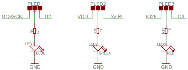
ArduiPi Led Schematic
As you can see LED are connected “classic” way, this means to lit them you need to set the GPIO or Arduino Port value to 1. Each LED can be driven by 2 ports depending on PLED Pad position. So you need to choose the one you want.
To be able to lit a LED you need to choose on what pin it need to be connected. To do so you need to put solder on the according LED pad to select which pin will drive the LED. The PAD are located on the bottom of the board, near the External Power connector
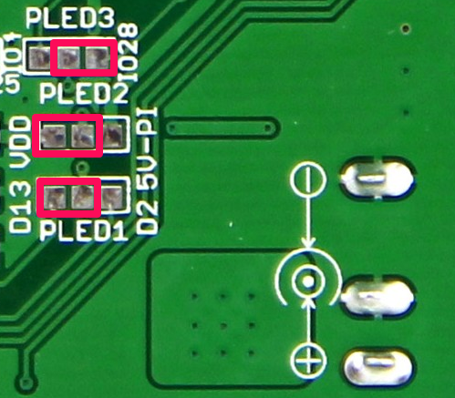
ArduiPi LED Pad Configuration
Here the available options :
- LED 1 is dedicated to Arduino side, it can be connected to D13 (default official Arduino LED setting) or D2. Edit 03/17/2014 : ArduiPi board V1.1 have D13 connection done by default
- LED 2 is dedicated to board Power, it can be connected to VDD or Raspberry PI 5V. If connected to VDD, the LED will be lighted as soon as Arduino is powered even if it is powered by external power, USB FTDI power, or Plugged into Raspberry PI (and PI powered of course). If connected to 5V-PI the LED will be lighted only when ArduiPi board is plugged into Raspberry PI AND PI is powered. Edit 03/17/2014 : ArduiPi board V1.1 have VDD connection done by default
- LED 3 is dedicated to Raspberry PI, it can be connected to GPIO4 or GPIO28 (GPIO28 is available only to Raspberry PI revision 2). Edit 03/17/2014 : ArduiPi board V1.1 have GPIO4 connection done by default
In the previous picture, if you put some solder on the PAD rounded by the red square, the LED 1 will work as classic Arduino (blink sample will work), LED 2 will indicate when there is power to Arduino and LED 3 will be connected to Raspberry PI GPIO 28
Powering the ArduiPi board
ArduiPi board can be used also as an classic Arduino board, this means that you do not need to plug it on a Raspberry PI (even if it as been designed for). For this you can power the board in differents ways.
- Powering With External Power
When you power the board with external power you can plug a external DC 7V to 16V into the corresponding barrel connector. The external connector is located on ArduiPi board at the following place :
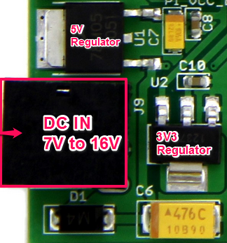
ArduiPi External Power
When you use external power, the two on board regulators on ArduiPi board are doing power conversion. One 5V and one 3V3, named respectivly 5V-EXT and 3V3-EXT on the following schematic :
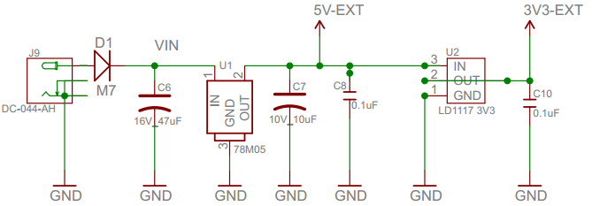
ArduiPi Power Schematic
When you use external Power it is not mandatory to plug ArduiPi board on Raspberry Pi, you can use the ArduiPi board as stand alone board. But, you need to tell ArduiPi board that you are using external power. This is done by selecting the on board switch. You need to position the switch PI_VCC_EXT (bottom switch of the picture below) to EXT position.
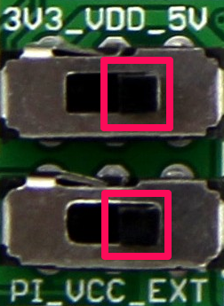
ArduiPi External Power Selection Switch
The top switch is used to select the value of the power that is provided to the AruiPi board. In the example of above picture, the power is set to 5V.
Note that even selecting 5V on the first switch the power applied to NRF24L01 connector is always 3V3, this is to protect the NRF24L01 chip that does not support more than 3.6V. So you don’t need to bother with level translation for NRF24L01 or Breakout board of the same type.
- Powering with FTDI Cable
Another way to power AdduiPi board is a classic FTDI Cable or FTDI Adapter. But for this to work, you need to solder a jumper (or close directly with a strap wire) on JVDD as follow, and put a jumper on it.
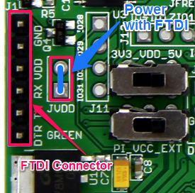
ArduiPi Power with FTDI
Once jumper in place, as USB cable power is connected to 5V-EXT signal, you need to position the switch PI_VCC_EXT to EXT position like when you power the board with external power.
Remember that FTDI usb cable can not provide too much current, so be carefull if you have a lot of devices on ArduiPi board, the power provided by the cable may not be enougth.
The FTDI cable need then to be connected on J1 connector of ArduiPi board. You can use any FTDI compatible cable such as this one, this one (shop), or this one. Take care of way of connection (it will not destroy anything if you reverse the connector). Green means DTR signal (connected to Arduino Reset line for Autoreset feature) the two first pins of J1 connector are ground.
- Powering from Raspberry PI
The last way to provide power is to use the Raspberry PI power. Of course, to be able to achieve this, the ArduiPi board need to be plugged onto Raspberry PI
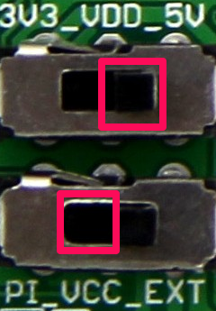
Selecting power from PI is done by selecting the on board switch. You need to position the switch PI_VCC_EXT (bottom switch of the picture below) to PI position
ArduiPi Power From PI
Take care that as previous case, depending on how much devices are connected to ArduiPi board, the PI power need to be adequate and may not be enought. If not, the Raspberry PI could not even be started. I had this case during the test phase when using grove OLED. So if PI is not starting, choose a good Power for it (1A minimal) and if it does not still work, power the ArduiPi board with external Power.
The top switch is used to select the value of the power that is provided to the AruiPi board. In the example of above picture, the power is set to 5V.
Uploading Sketches to Arduino
The Arduino on ArduiPi board is Uno compatible, this means that to upload sketch on it, you need to select the board Arduino Uno into Arduino IDE
- With FTDI Cable from PI or other computer
Connect a FDDI cable (from PI USB or another USB computer) to J1 connector of ArduiPi board. For this to work, ArduiPi board should be powered (see how to at previous step above). If you program from another computer, this is the only way to burn sketch on Arduino (except using ICSP but that’s not the deal of the board).
This method is fine and quick, but if your IDE is located on your PI you will need one USB port to connect FTDI cable, which took 50% of USB ports of PI (since it has only 2). So the next method could save you one USB port and one FTDI cable.
- Directly from Raspberry using Raspberry PI integrated UART
Raspberry PI as a onboard serial port used by the console, you can get this port for you own and to program the Arduino. For this, your Arduino IDE should be on your Pi (or you will need to transfer generated HEX file from external Arduino IDE).
To enable Raspberry PI onboard serial UART you need to do two things:
- Configure the serial port of Raspberry PI to be available to user. Use this guide to do this
- connect RX and TX lines from PI to Arduino. For this you just need to solder wire, or jumper (strongly recommended, see below why) on JTXD and JRXD as follow..
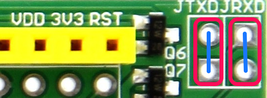
ArduiPi connect Arduino to Raspberry Serial
The connector is located on top left of the board. Once this is done, everything is not yet ready.
Pay attention doing this, because after it’s done, if you still want to use FTDI cable to program Arduino, you will need to remove the 2 connections (because if not, RX/TX from FTDI will conflict with RX/RX from PI), that is why I strongly suggest to put jumpers on JTXD and JRXD instead of soldering wires, it’s then easier/quicker to put or remove them.
/dev/ttyAMA0 is not reconized by Arduino IDE, so we will link it like a real serial device. Connect to your Pi and issue the following command.
sudo ln -s /dev/ttyAMA0 /dev/ttyS0
This will create a “real” serial device /dev/ttyS0
Edit : This command seems not be be “reboot persistent” (thanks Bob for the information), so lost after a reboot. If you want to keep ttyS0 after reboot, just add the following line to /etc/rc.local file (just before the line “exit 0”)
ln -s /dev/ttyAMA0 /dev/ttyS0
A more “clean” way would be instead creating a udev rule file, for example: create a file named 88-serials.rules into folder /etc/udev/rules.d/ containing the following code
KERNEL=="ttyAMA0",SYMLINK+="ttyS0" GROUP="dialout"
with both described solutions, device /dev/ttyS0 will be there after reboot
Now you can use the /dev/ttyS0 as serial into Arduino IDE. But, this method does not Auto-Reset the Arduino to be ready to auto upload Firmware, this means that you will need to use “old school” sync with manual push of reset button from ArduiPi board when uploading sketch from Arduino IDE.
But, ArduiPi is a so featured board that you can use a PI GPIO connected to DTR signal to send reset to Arduino. This permit like with a FTDI cable, to compile and upload sketch directly from Raspberry PI Arduino IDE with no manual step. To do this, you need to connect DTR pin of FTDI connector to a GPIO port of Raspberry PI. I choosed GPIO18 but you can change as you want the GPIO port used.
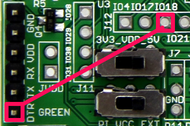
ArduiPi Enabling Arduino Auto-Reset with GPIO
The picture above show you what is needeed to enable Auto-Reset Feature. Edit 03/17/2014 : ArduiPi board V1.1 have this connection done by default, no need to wire. If you want to remove this feature you will need to cut the AUTORST trace PAD on ArduiPi V1.1 board.
Doing hardware wiring is not enought, you need to do software patching because the tool used to program the Arduino (avrdude) can’t drive DTR pin of the PI serial port to Reset Arduino but Raspberry PI integrated UART does not have this DTR signal available (this is why we need to use one GPIO pin). So we need to tell the tool that a GPIO is used to drive DTR (reset) signal.
For this you need to install Python Raspbery Pi GPIO package and some custom scripts and avrdude if you do not have Arduino IDE installed (issuing a apt-get install avrdude).
First we rename original avrdude program to avrdude-original, next install a new python script named avrdude-autoreset and then create a link named avrdude to point on avrdude-autoreset. This new script will launch another script called autoreset which does the reset Arduino and then launch the original avrdude program just after the DTR (reset) line has been pushed low by the GPIO 18.
You can do all of this by doing the following commands when connected to Raspberry PI (can be done also with SSH)
Edit 04/04/2014 : Seems executing the command
apt-get install python-rpi.gpio
does not install the latest version of rpi.gpio and thus can fire up some warnings when executing autoreset (but still works) so the best solution is using
easy_install rpi-gpio
. I updated the following procedure to use this command.
sudo apt-get update
sudo apt-get install python-setuptools
sudo easy_install rpi.gpio
wget https://github.com/hallard/arduipi/raw/master/raspberry/autoreset
wget https://github.com/hallard/arduipi/raw/master/raspberry/avrdude-autoreset
wget https://github.com/hallard/arduipi/raw/master/raspberry/reset-arduino
sudo mv /usr/bin/avrdude /usr/bin/avrdude-original
sudo cp autoreset /usr/bin
sudo cp avrdude-autoreset /usr/bin
sudo cp reset-arduino /usr/bin
sudo chmod ug+x /usr/bin/avrdude-autoreset
sudo chmod ug+x /usr/bin/autoreset
sudo chmod ug+x /usr/bin/reset-arduino
sudo ln -s /usr/bin/avrdude-autoreset /usr/bin/avrdude
PS : If you want to change the GPIO line used you need to change the line “pin=12” in autoreset python script. The value 12 is the Raspberry PI connector P1 pin number in our case and not the GPIO name, take care !. You can see pins definition here :

Most of this stuff about autoreset was grabbed from Internet, I do not remember where but I’d like to thanks the original author of theese scripts which I’ve tweaked.
Now you can upload sktech directly from Arduino IDE. Of course if you have any hex file compiled on another computer (like me, I do not have Arduino IDE on Raspberry, I only use SSH on py PI), you just need to copy your hex file to Raspberry and launch the avrdude command line like the following :
root@pi03:#avrdude -v -c arduino -p ATMEGA328P -P /dev/ttyS0 -b 38400 -U flash:w:RFM_PI_Gateway.cpp.hex
Change the baudrate to the one used by your bootloader, here a specific example card is set to 38400 kbps but in case of ArduiPi board, it should be 115200 (UNO bootloader) instead of 38400.
And here the following result of avrdude
avrdude-original: Version 5.11.1, compiled on May 23 2012 at 11:08:25
                  Copyright (c) 2000-2005 Brian Dean, http://www.bdmicro.com/
                  Copyright (c) 2007-2009 Joerg Wunsch

                  System wide configuration file is "/etc/avrdude.conf"
                  User configuration file is "/root/.avrduderc"
                  User configuration file does not exist or is not a regular file, skipping

                  Using Port                    : /dev/ttyAMA0
                  Using Programmer              : arduino
                  Overriding Baud Rate          : 38400
                  AVR Part                      : ATMEGA328P
                  Chip Erase delay              : 9000 us
                  PAGEL                         : PD7
                  BS2                           : PC2
                  RESET disposition             : dedicated
                  RETRY pulse                   : SCK
                  serial program mode           : yes
                  parallel program mode         : yes
                  Timeout                       : 200
                  StabDelay                     : 100
                  CmdexeDelay                   : 25
                  SyncLoops                     : 32
                  ByteDelay                     : 0
                  PollIndex                     : 3
                  PollValue                     : 0x53
                  Memory Detail                 :

                                           Block Poll               Page                       Polled
                    Memory Type Mode Delay Size  Indx Paged  Size   Size #Pages MinW  MaxW   ReadBack
                    ----------- ---- ----- ----- ---- ------ ------ ---- ------ ----- ----- ---------
                    eeprom        65    20     4    0 no       1024    4      0  3600  3600 0xff 0xff
                    flash         65     6   128    0 yes     32768  128    256  4500  4500 0xff 0xff
                    lfuse          0     0     0    0 no          1    0      0  4500  4500 0x00 0x00
                    hfuse          0     0     0    0 no          1    0      0  4500  4500 0x00 0x00
                    efuse          0     0     0    0 no          1    0      0  4500  4500 0x00 0x00
                    lock           0     0     0    0 no          1    0      0  4500  4500 0x00 0x00
                    calibration    0     0     0    0 no          1    0      0     0     0 0x00 0x00
                    signature      0     0     0    0 no          3    0      0     0     0 0x00 0x00

                  Programmer Type : Arduino
                  Description     : Arduino
                  Hardware Version: 3
                  Firmware Version: 5.0
                  Vtarget         : 0.3 V
                  Varef           : 0.3 V
                  Oscillator      : 28.800 kHz
                  SCK period      : 3.3 us

avrdude-original: AVR device initialized and ready to accept instructions

Reading | ################################################## | 100% 0.01s

avrdude-original: Device signature = 0x1e950f
avrdude-original: safemode: lfuse reads as 0
avrdude-original: safemode: hfuse reads as 0
avrdude-original: safemode: efuse reads as 0
avrdude-original: NOTE: FLASH memory has been specified, an erase cycle will be performed
                  To disable this feature, specify the -D option.
avrdude-original: erasing chip
avrdude-original: reading input file "RFM_PI_Gateway.cpp.hex"
avrdude-original: input file RFM_PI_Gateway.cpp.hex auto detected as Intel Hex
avrdude-original: writing flash (16048 bytes):

Writing | ################################################## | 100% 5.64s

avrdude-original: 16048 bytes of flash written
avrdude-original: verifying flash memory against RFM_PI_Gateway.cpp.hex:
avrdude-original: load data flash data from input file RFM_PI_Gateway.cpp.hex:
avrdude-original: input file RFM_PI_Gateway.cpp.hex auto detected as Intel Hex
avrdude-original: input file RFM_PI_Gateway.cpp.hex contains 16048 bytes
avrdude-original: reading on-chip flash data:

Reading | ################################################## | 100% 5.13s

avrdude-original: verifying ...
avrdude-original: 16048 bytes of flash verified

avrdude-original: safemode: lfuse reads as 0
avrdude-original: safemode: hfuse reads as 0
avrdude-original: safemode: efuse reads as 0
avrdude-original: safemode: Fuses OK
I also included a reset script to reset Arduino without having to program it, it’s called reset-arduino. You can launch it by the following command (but you need to have installed Wiring Pi library for this one)
root@pi03:~# reset-arduino
Resetting...done
root@pi03:~#
Do not hesitate to look at this script (/usr/bin/reset-arduino) , you can also launch a serial terminal just after the reset (that is what I do every time to check all is fine) if you want to see serial.Print event out from Arduino.
To be continued
This post will be updated soon with more documentation about all ArduiPi features. Drop me a comment if you need to do something that is not yet documented, I will write documentation as soon as you will need it. I’m really missing time on the moment due to a huge optimized project with ArduiLed board.
Charles