For some time now, I’m using great RFM12B RF modules to transmit data from my nodes to my gateway and then post data to emoncms.
I started to play with Jeelabs library but switched to Felix (lowpowerlab.com) library improvement on. Both are working fine and have similar functionalities but Felix’s one has some refactory improvement such as setting some parameters (power, speed, …) from calling function instead of doing this in “compilation”. Moreover Felix’s library has possibility of using 127 nodes on same network instead of 30. Take care that both libraries are not compatible each other. This mean that one packet sent by one library can’t be received by the other due to different packed handling in headers. See jeelabs packet format and Lowpowerlab packet format if you want to have more information.
Also, no library have a function to read analog RSSI from RFM12B. This is understandable because the module does not provide this information as is. But RFM12B has a pin on chipset that presents the extremely interesting analog RSSI signal which can show us the level of signal reception. But this pin is not available out of the box so we need to tweak to bring it to us. There is a fast and easy way to get this signal and connect it to an analog pin of an Arduino. We just need to solder a wire. Welcome now to Murphy’s law, it’s not so simple because depending on RFM12B module type, the ARSSI signal is not located on same place and have the same value. Even if it is always on ARSSI capacitor on both module type, I saw that it is reversed from one module to other. Check the picture below :
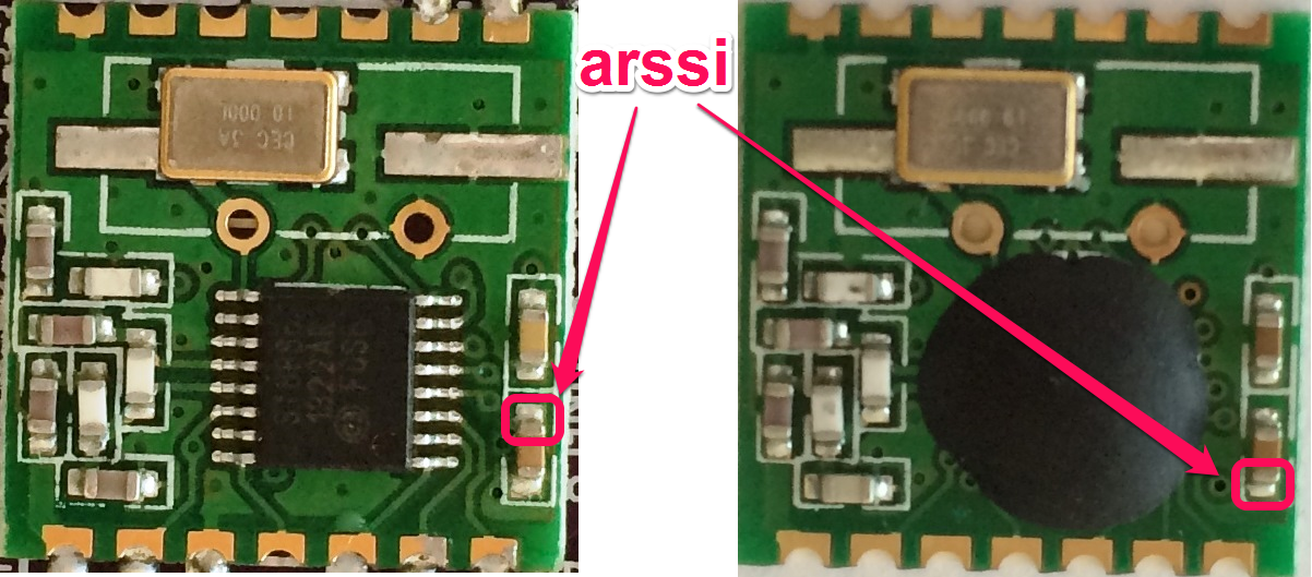
RFM12B arssi signal location
To be sure just put a voltmeter on both end of ARSSI capacitor. The ARSSI pin will be the one that reading should be between +300 mV and +600 mV when no RF signal is present. So try to do this with no RF signals around to know the ARSSI idle voltage (we will need it later in the library). This signal can be moving and can also grow up to 1.2 V if RF signal is present if another device is doing some transmit in the same frequency range at the same time. Typical ARSSI voltage can be as follows depending on chipset, this is why it’s important to measure it idle value to have accurate results :
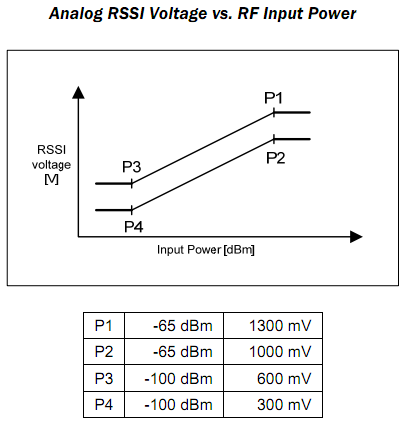
RFM12B ARSSI Signal Range
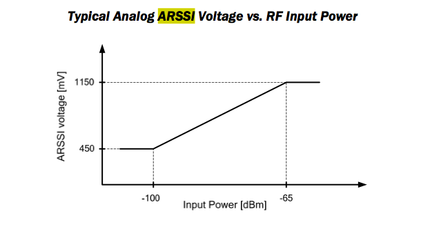
RFM12B ARSSI Typical
This is why I started to improve this library to provide this new functionality and had some other features. I started from Felix’s library as code base.
Library enhancements
This library is called RFM12B_arssi to avoid same name and confuse Arduino IDE. This mean you need to add the following line at the beginning of your Arduino sketch (after installing the library in Arduino).
#include <RFM12B_arssi.h>
Here a list of new features implemented in this new version of the library.
- Added accurate ARSSI reading (need hardware hack soldering wire to one analog entry of choice)
- Added dynamic Chip select Pin selection of RFM12B
- Added dynamic IRQ pin selection of RFM12B
- Added check that RFM12B module is present on board
- Update 08/29/1014 : Added ATMega 1284p External Interrupt compatibility (INT0, INT1, INT2). You need to install and use Felix’s Mega Core for Arduino Ide to use them on 1284
- Update 08/29/1014 : Added time-out to initialize function to avoid lockup, Initialize(..) returns false if timed out now.
- To Do : Add a promiscuous mode
New Features
I did not changed anything on function calls so this library should be compatible with Felix’s one without any problem.
By default this new library assume that RFM12B CS pin is connected to D10 (SS) and RFM12B IRQ connected to D2 but you can change this with the following.
Here are the new features :
- SetCS( arduinoPin )
This is for choosing the CS pin where is connected the Chip Select pin of the RFM12B. Arduino pin is Arduino format (5, 8, … A2, ..)
Warning : This call should be done before any Initialize(…) standard code
- SetIRQ( irqPin )
This is for choosing the Hardware IRQ pin where is connected the IRQ of the RFM12B. You can only use with external hardware IRQ of Arduino, so for :
ATMega328 it’s 2 for IRQ Pin 2 (INT0) and 3 for IRQ Pin 3 (INT1).
ATMega1284 it’s 10 for IRQ Pin 10 (INT0), 11 for IRQ Pin 11 (INT1) and 2 for IRQ Pin 2 (INT3).If you want to use the pin change IRQ (not tested) you need to uncomment the line//#define PINCHG_IRQ 1
defined in RFM12B_arssi.h file (same as before)
Warning : This call should be done once before any RFM12B Initialize(…) standard code
- isPresent( cspin, irqpin )
Check if RFM12B device is present, return true if RFM12B device is detected using the cspin and irqpin false otherwise (same format as above)
This call inside call SetCS and SetIRQ so if you call isPresent you can avoid calling SetCS and SetIRQ. If you call isPresent without parameters it assume that the RFM12B module is connected with default values (CS=D10 and IRQ=D2) - SetRSSI( analog_pin, arssi_idle )
Configure the ARSSI, analog pin used in format used by ATMEL ADMUX register. So 0 for A0 to 7 for A7
Define the value of ARSSI (in mV) when in idle mode (not receiving anything), see explanation above. If arssi_idle is set to 0 (default) the ARSSI measuring feature is disabled inside the RFM12B receive routine. If you measured the Arssi idle value to 450mV for example, the parameter arssi_idle should be 450.
Some constants are defined for this in RFM12B_arssi.h#define RF12_ARSSI_300mV 300 #define RF12_ARSSI_450mV 450 #define RF12_ARSSI_600mV 600
Warning : As ARSSI analog measurement is done by interrupt (ISR) routine during RF reception, the ISR code select the correct ADC (ADMUX) channel to issue the measure. unfortunately if your main code is using also the ADC (and probably on another channel) this can break up your main code measurement. This is why I added the function below :
- noRSSI( state )
If parameter is true, prevent RFM12B driver to issue analog measurement on ARSSI value until noRSSI is called with false argument.
Typical use is as follows :// Indicate RFM12B IRQ we're doing conversion, so ARSSI reading from now radio.noRSSI(true); // This will select correct channel and issue a conversion // but we will ignore 1st result. we let time to settle ADC // remember we do not know ADC channel configuration here // so select it (need to be done after noRSSI call) analogRead(A2); // now we're ready, read value value = analogRead(A2); // we done with ADC // Enable back ARSSI reading from now radio.noRSSI(false);
- ReadARSSI( vcc )
Return the RSSI value of the last received frame from RFM12B, to determine the correct value, the function need to know the voltage of Arduino. This is the vcc parameter (in mV). If your Arduino is powered with 5V call it with ReadARSSI(5000) and for 3V3 ReadARSSI(3300).
Return value is RSSI from -100 to -65 in dB. Special values constants are :#define RF12_ARSSI_ABOVE_MAX -64 // Arssi value above maximal value #define RF12_ARSSI_BELOW_MIN -101 // Arssi value below minimal value #define RF12_ARSSI_RECV -102 // Can't get Arssi because we're not in idle mode #define RF12_ARSSI_BAD_IDLE -103 // Arssi idle mv is not in 300mV and 600mV #define RF12_ARSSI_DISABLED -104 // Analog RSSI not used #define RF12_ARSSI_NB_BYTES -110 // Not have enough bytes received to calculate ARSSI
Note : If you’re battery-powered, your voltage may decrease and so, not always be the same. In this case, to determine current voltage please read this article from Scott Daniels to see how to get value of VCC. If you use this, do not forget to add both noRSSI (true to start, false to end) into ADC reading when you want to read VCC. See on sample example below code on how to do this.
- getRSSIIdle()
Return the value of arssi_idle (internal var of the library) set by the function setARSSI() in mV.
If 0 the ARSSI function is disabled. - getRSSIAnalogPin()
Return the value of ARSSI Analog pin (ie 0 for A0, …, 7 for A7)
Examples
I’ve tweaked the originals examples of RFM12B_Struct_gateway and RFM12B_Struct_node from Felix to add RSSI reading from the gateway. I used most of the new features to show how to drive them.
I’ve also added some other stuff such as Vcc calculation, accurate ADC reading using noise reduction and sampling, reading internal Arduino temperature, …
Theses values are sent by the node to the gateway. When received, the gateway get RSSI value and send back to node the RSSI value. Bargraph of RSSI is then printed on serial for both gateway and node.
Here some results output :
RFM12B Detected OK!
Transmitting at 433Mhz...
ARSSI Enabled
Connect ARSSI signal on Analog pin 0 of this board
ARSSI idle voltage is set to 350 mV
SPI Flash Init FAIL! (is chip present?)
Vcc = 3349 mV
temp= 17.70 C

Quick command summary, type it any time
  d : dump flash
  e : erase flash
  i : print flash ID
  v : read and display VCC
  t : read and display temperature
  a : measure and display a set of ARSSI Analog Pin 0)

Waiting for receiving data from node ...

Received struct[10] From nodeID 99 with { temp=21.00 C  Vcc=3215 mV uptime=1 s } ACKED
RSSI [=================================   ] -68 dB Sending back RSSI to nodeID 99 ... waiting for ACK...ok!
Received struct[10] From nodeID 99 with { temp=21.00 C  Vcc=3215 mV uptime=0 s } ACKED
RSSI [=================================   ] -68 dB Sending back RSSI to nodeID 99 ... waiting for ACK...ok!
Received struct[10] From nodeID 99 with { temp=20.20 C  Vcc=3215 mV uptime=1 s } ACKED
RSSI [=================================   ] -68 dB Sending back RSSI to nodeID 99 ... waiting for ACK...ok!
Received struct[10] From nodeID 99 with { temp=21.00 C  Vcc=3215 mV uptime=2 s } ACKED
RSSI [=================================   ] -68 dB Sending back RSSI to nodeID 99 ... waiting for ACK...ok!
Received struct[10] From nodeID 99 with { temp=21.00 C  Vcc=3215 mV uptime=3 s } ACKED
RFM12B Detected OK!
Transmitting at 433Mhz...
ARSSI Disabled for this board
SPI Flash Init FAIL! (is chip present?)
Vcc = 3224 mV
temp= 21.00 C

Quick command summary, type it any time
  d : dump flash
  e : erase flash
  i : print flash ID
  v : read and display VCC
  t : read and display temperature

Starting to send data to gateway ...

Sending struct[10] To nodeId 1 with { temp=21.00 C  Vcc=3215 mV uptime=0 s } ... waiting for ACK...ok!
[1] RSSI [=================================   ] -68 dB ACKED
Sending struct[10] To nodeId 1 with { temp=20.20 C  Vcc=3215 mV uptime=1 s } ... waiting for ACK...ok!
[1] RSSI [=================================   ] -68 dB ACKED
Sending struct[10] To nodeId 1 with { temp=21.00 C  Vcc=3215 mV uptime=2 s } ... waiting for ACK...ok!
[1] RSSI [=================================   ] -68 dB ACKED
Sending struct[10] To nodeId 1 with { temp=21.00 C  Vcc=3215 mV uptime=3 s } ... waiting for ACK...ok!
[1] RSSI [=================================   ] -68 dB ACKED
Sending struct[10] To nodeId 1 with { temp=21.00 C  Vcc=3215 mV uptime=4 s } ... waiting for ACK...ok!
[1] RSSI [=================================   ] -68 dB ACKED
All examples code are located on my github in RFM12B_arssi repository. you can also find the two following examples at the same place.
- RFM12B_Struct_gateway_arssi : Receive data then read RSSI and send back to node RSSI value
- RFM12B_Struct_node_arssi : Read some values, send to gateway then receive RSSI value
Reference
Thanks to all contributors starting Jean-Claude Wippler from jeelabs for writing original Library.
- Felix Russu from lowpowerlab for providing more flexibility to it and Mega Core for 1284p.
- Strobotics RFM12B hardware interface with some ARSSI description
- Marc for reading ARSSI signal of RFM12B and RFM12B chipset advanced description
- Scott Daniels for Secret Arduino Voltmeter – Measure Battery Voltage
Let me know if you have any question or improvement, I’d be glad to see other ARSSI results.
Charles