Following the previous article presenting the ULPNode it’s now time to deep into the technique used to setup the starting mechanism of ULPNode bootloader. In this 1st part I’m introducing the goals to achieve and in the 2nd how it has been done with all source code.
Specifications of ULPNode
We will be using all the features provided by these little chip used on well known Arduino, the Atmel ATMega328P. The P version of this chip is used (PicoPower) because this is the model that permit to achieve so low consumption. Then it will be used to the edges defined in the datasheet. So it will be able to work starting 1.8V and it maximum voltage will be 3.3V. Why 3.3V, well it’s the voltage used by most digital sensors and also by the radio modules that it will be able to drive (RF12B, RFM69 or NRF24L01)N
Now looking at the datasheet, and well known graph following from Atmel showing Voltage VS Frequency
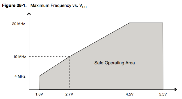
ATMega328P Frequency VS Voltage
We can see that the only way to be able to work at 1.8V is to set Frequency to 4MHz. So cruising speed of ULPNode will be defined to 4MHz. But don’t worry, ULPNode boards have 16MHZ crystal on board, this mean that if you need to do critical timing or speed operation it will be possible to ULPNode to work at 16MHz. You will just need to be sure to enable the correct hardware to bring Voltage to 3.3V before setting High Speed operation, and once done, cut it off to go back to 4MHz.
Bootloader configuration : Magic of Fuses
Now that the specifications are defined, we need to prepare them to be understandable by the ATMega328P. This chip has some configuration definitions called Fuses that define how the chip will work and what features we want to use. I will not talk a lot about fuses here, others have already described. Just take a look to Adafruit Fuses tutorial if you want to have more information.
As previously said, as ULPNode can run at 1.8V we should not go over 4MHz at startup. This is why we will be using the specific fuse called CKDIV8 which set the clock prescaler to divide the clock by 8. This mean that at startup ULPNode will by default run at 2MHz (16MHz / 8) which is quite on specification.
The other point is that we need to be able to do, it’s to increase the clock while into the bootloader because you will see later that we need to get to 4MHz or more. This is quite simple using the functions provided by the compiler, but it has a drawback. The original Bootloader is just under 0.5Kb and as soon as you want to use clock change function size is increasing and can’t be fitted on 0.5Kb (may be it could but as I need to add more things onto the bootloader, never mind, I will use 1Kb bootloader). This is why I used BOOTSZ fuse to 512W_3E00. (512 words, so 1024 bytes of bootloader). This will reduce maximum sketch size by 512 bytes regarding the original optiboot bootloader, but it will not wasted because I will include some code into the bootloader that will be callable from Arduino sketch using advanced features such as vector table.
Of course to be able to work from 1.8V we need to set the BOD fuse to 1.8V, if not, it won’t start at 1.8V and I strongly discourage to disable the Brown Out Detection (except before entering Low Power idle mode). So I’ve set up the BODLEVEL fuse to 1.8V
The last fuse I changed (regarding Arduino default fuses) is the SUT_CKSEL to be able to speed up startup and wake up from sleep modes faster. I’ve setup the 0MS startup. As we have BOD enabled, in all cases, the chip will not start above 1.8V and at this point the Crystal Oscillation will be started correctly (well I saw this somewhere in the datasheet).
Here a screenshot of the fuses values used by ULPNode
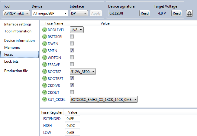
ULPNode Fuses settings
Hardware involved
Ok, now let’s continue, what hardware we need to drive into the bootloader? Well first of all, I love LED, they can give you lot of information on what is going on when you debug the code and sometimes on end user to view things (transmitting for example). I know it’s far away from Low Power but you don’t need to enable them. They are on board if you need, that’s all. But one led is not really sufficient, I like to have three (Red, Green, Blue) but this requires 3 I/O pins, and I do not want to use 3 just for LEDs.
On board classic LED becomes RGB, welcome to WS2812B LED
I decided to replace the classical on board led with the new RGB WS2812B LED (the one used on addressable RGB Led Strips). The WS2812B has all that is needed to drive in it integrated chipset and it is driven with just one pin. On ULPNode, the WS2812B is connected to D6 Arduino pin (PD6). The WS2812B code is included into the bootloader (fancy different flash color indicating what’s going on) and of course if you need to light the WS2812B led from you sketch you just need to call the exported function. It is even possible to chain this WS2812B led to a strip to drive multiple LED. Schematic is following :
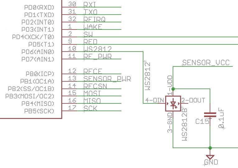
ULPNode WS2812B Led
Powering all devices on demand
The second change is nothing new or fancy, just the possibility to totally turn off devices and sensors from the power so devices are not harvesting any power. This is done by controlling a P-MOSFET connected to a I/O pin of the Arduino. When the pin is HIGH power is disconnected from devices and when it’s low power reach the devices and they can work as usual. ULPNode use 2 pins for this :
- D7 for powering the Radio Module (RFM12B, RFM69, NRF24L01), note that radio modules have sleep mode, so it’s not mandatory to use this powering technique. You can also let the pin low and your radio module always powered using sleep mode, depending on you needs.Once again, if you need it, it’s on board.
- D9 for powering the “sensors” (NTC, LDR, PTC, Analog, ..) and all others (I2C, WS2812B LED)
Here are the schematics that correspond to this description :
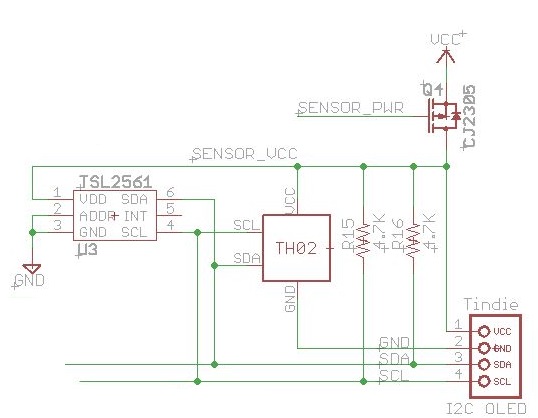
ULPNode Digital Temp & Humidity (TH02) , Luminosity (TSL2561) Sensors and I2C Oled
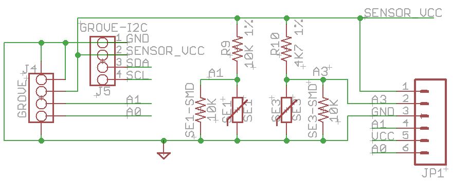
ULPNode Analog Sensors (SMD or PTH are available on board for each) and grove connectors
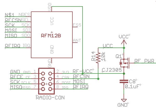
ULPNode Radio Power (R14 used as pullup to avoid problem when flashing bootloader)
I need power, please set myself to 3.3V
This one is more new and tricky, this will enable the on board DC booster to activate and thus bring the voltage of the main board to 3.3V. This permit doing all needed harvesting operations in a safe and working voltage range. This is also the mode that permit to bring the clock to 16MHz for example. Once we’re done, we need disable the booster mode. Explanation and schematics of this point will be described later since it also involve other hardware chip than the DC booster.
In the next article, I describe the code implemented and the modification done into the original optiboot bootloader.
For the fun, just a picture of implementation and testing new bootloader code. Look at Diavolino board, I love them, nothing more than the chip, crystal, and the LED with a ICSP connector, perfect for testing the LED driver.
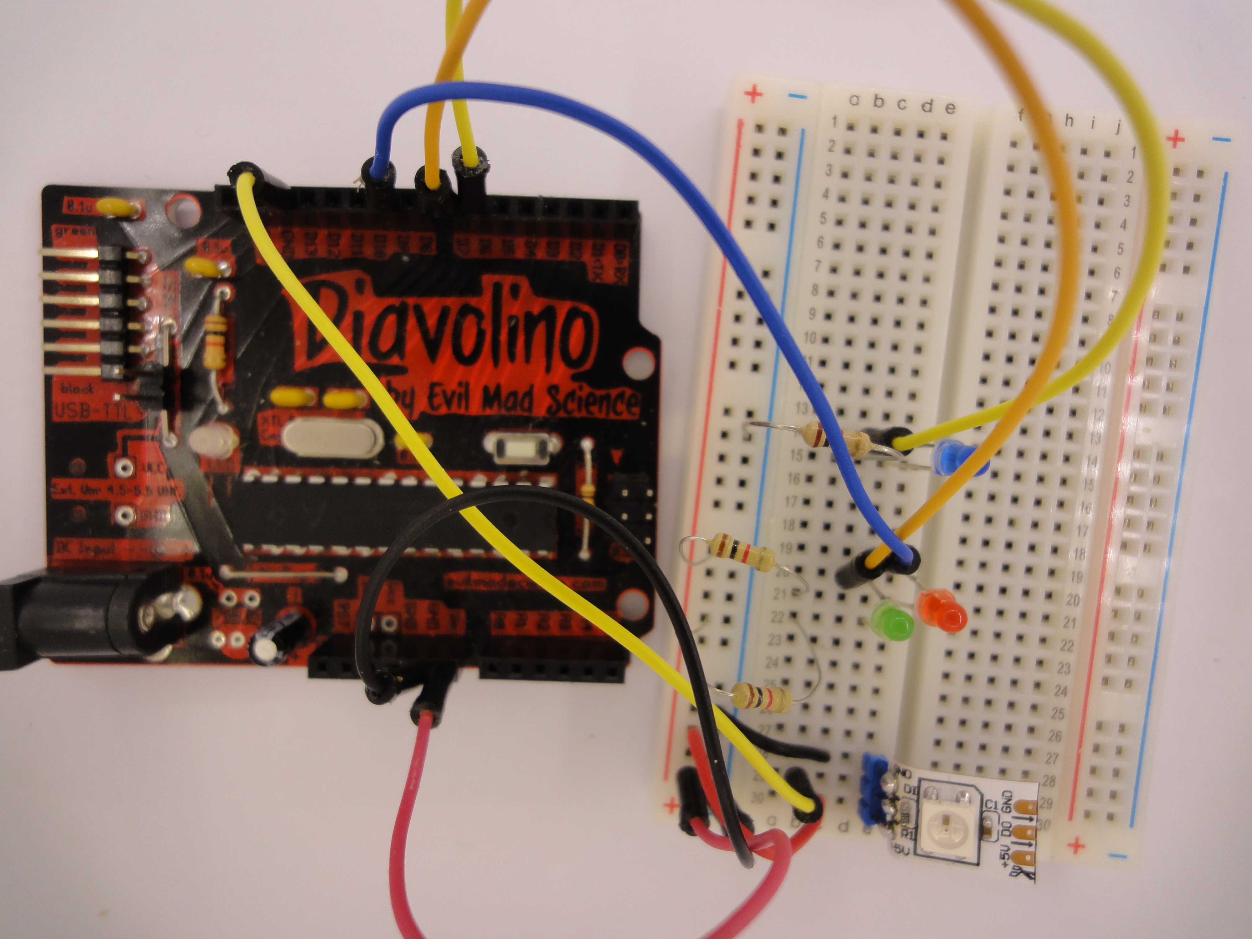
ULPNode Bootloader Testing
Reference
To create ULPNode I’ve also spent time for reading and learning from different sites about the subject, here are the most source sites, blogs, code, and other useful information
- Excellent post from Mick Gammon on Low Powering Technique
- Huge work done by JC Wippler from jeelabs with jeenodes and some powering techniques. You will find lot of articles on jeelabs site, it’s from my point of view one of the master site reference over the net.
- Felix Russu for the well known Moteino boards available at LowPowerLab site and the new RFM69 library
- Martin Harizanov with his Funky boards and good low power coding