Why this new project ?
For some time being, I researching a way to have to have a kind of “universal” Arduino node sensor. When I say universal, I’m talking about connecting to it several sensors type (Temperature, Humidity, Lux, … such as LDR, NTC, PTC, DHT11, DHT22, DS18B20, I2C sensors). I found a lot on the net, some very interesting and fine products such as Moteino, Anarduino miniwireless, Jeenode, but as today, none are especially made for ultra low power with long battery life when using classic battery such as one AAA, CR2450 or CR2032 Cell Coin. So not using Lipo, or any rechargeable batteries.
At 1st research I tried lot of them, it works fine, but as soon as you want to power them with classic battery (one AAA, CR2032, …) you’re facing other challenges, be able to maximize the battery life and also be able to send wireless frames until battery is reaching it’s end of life.
I’ve also tested several RF modules such as RFM12B, RFM69, NRF24L01 and results are the same, this is logical since the power consumption reach the max when these modules are sending data over the air.
Challenges faced off.
Of course the battery life depends on accurate and optimized code for sleeping mode but during my prototyping I also saw that the conception of certain type of battery can cause node stopping sending data even if the battery has enough power (voltage). This is due to the internal resistor (IR) specially on cell coin battery (see this post for detailed information). When sending data, you may need to have peak current that will create a drop voltage on the internal resistor, this voltage drop can be large enough to stop wireless module to send frame. For example, imagine a CR2032, with 20 Ohm internal resistor. Let’s say that battery is running for some time and it’s voltage it’s about 2.6V, this mean the battery if far away from it’s end of life. When the node activate the wireless module to send data (example RFM12B) the consumption can reach 25 mA, this mean that 25 mA across 20 Ohms IR drop 0.5V, this drive your powered node driven by 2.6V – 0.5V = 2.1V which is under the RFM12B minimal voltage (Datasheet says 2.2V) and thus, this does not work anymore (in fact your node is working, but is unable to transmit frame to a gateway).
How to achieve the challenges ?
This is why decided to try to create a wireles node that remove all these limitation and that works very long time, until battery really reach it’s end of life. The challenge was strong enough but I can say now that it has been reached. I’ve been working and testing different prototype and technique until I found “the one”. I do not know if it’s the best, but this new one works fine. For this I also needed to change lot of things over “basic” Arduino wireless node. What I’ve done is detailed on the following steps :
- Redesign and create a new hardware Arduino board to provide Ultra Low Power features and reduce the idle mode consumption to minimal
- Change Optiboot bootloader to use the new hardware, reduce current consumption at boot up and add some features
- Write rock solid Ultra Low Power code to drive multiple sensors and send node data over the air. Add configuration of sensors type and node stored into the node eeprom so you won’t need to flash firmware to change any settings of the node.
- Create a Hardware Gateway (Arduino receiver based) to receive and do job with received information from sensors. The gateway can be of course any Arduino with wireless module (same of the sensor node of course), no specific need on this point, but I created PCB to fit into Raspberry Pi connector or TPLink routers such as WR-703N or MR-3022.
- Write Gateway code for Arduino receiver that will send data over the serial
- Create scripts on gateway that pool serial and to send data (emoncms for example) to have some graph. Of course, emoncms it’s just an example, you will be able to do whatever you want with the gateway and use any of existing piece of software capable of grabbing data received from serial port, such as node-red, python, perl,… . It’s really open to any existing software such as home automation.
Challenges reached.
I’m currently working on the 4st prototype generation and near to the mass production. Since it’s really a new product on the market (I did not found any one existing but if you know one, I will be interested to see), I hope it will wake up some kind on interests on the community. Of course if it can do a lot, it can do less, so ULPNode has also been designed to work in always powered mode (using it as a Gateway for example) or in always receiving Node mode (to be able to remote control things when receiving specific commands).
All the project will be open source, hardware and software, I will release the schematics and the code as soon as I will have the first batch of node produced.
The product will we called ULPNode, for Ultra Low Power Arduino Node and here are the features currently working on ULPNode :
- Standalone self powered hardware management engine that can also be controlled by the ULPNode firmware. This is the core and the most advanced ULPNode feature.
- Multiple battery support (CR2032, CR2450, one AAA, CR123) depending on what you wand to do with the node.
- For example CR2032, CR2540 or one AAA works fine for “sending only” node, It’s the lowest consuming node and ULPNode was designed for this mode.
- But if you want add more functions such as a node always listening to react to incoming data, it’s better to have stronger battery such as CR123, because this mode consume much more power (due to the radio module that is always powered)
- High range of input voltage, for always powered Node for example, or Node powered by Lipo (that can reach 4.2V on the input)
- Can work even with battery indicated as “dead” or “low bat” by other devices (Oregon Scientific sensors for example), this make this product type as “Green” and working with old battery so it won’t cost you any $ to power the module if you can grab some old battery.
- Radio module use 8 pins standard NRF24L01 connector type and RFM12B/RFM69C solder pad on bottom side. You will be able to put directly a NRF24L01 radio module but I will make available RFM12B and RFM69 boards (with flash memory) that fits on this connector.
- Will work with classical RF library depending on the wireless module used such as Felix’s from lowpowerlab RFM69, modified RFM12B library or even RadioHead library from Mike.
- Large various sensors can be used (Temperature, Humidity, Luminosity, Thermistance, LDR, NTC, PTC and also digital sensors such as DS18B20, TH02, DTH11, I2C sensors ….). Board is designed to simply place the sensors on it.
- Accurate Analog sensor reading with 1% precision pullup resistors and integrated Steinhart–Hart coefficient calculated for several type of sensor (see how to get the coefficient there). New device coefficient can be added easily.
- Onboard Thermistor 1% always available to be able to do temperature compensation with the Radio module (RFM69)
- Firmware configuration stored in EEP and accessible with Serial configuration mode, this mean that it can be used on other boards type without “conditionnal” compilation. You can setup which sensor to use, which type of NTC, LDR, pins where are connected the sensor, the Radio module type. …) No need to reconfigure after flash, the configuration will be kept and dedicated to the node in EEP
- Advanced low power battery reading with pad selectable divider (ex 1.5V AAA over 3.7V Lipo) to have an accurate ADC range measure.
- Powering / Unpowering sensors and Radio module to reduce consumption to minimal into sleep mode.
- 2 x Free analog/digital input/output with 1% precision pull up to connect various sensor type (NTC, LDR, PT1000, Thermistor, DHT11, DS18B20). These I/O can be also used as input/output to make pulse counter for example
- 1 x I2C grove connector
- … May be some other surprises…..
Now just to keep your interest, I want to let you know that my currently working nodes under testing with one old AAA battery are sending sensor frame (temperature and luminosity) approx every 30 seconds to my gateway. And the consumption on the AAA battery is about 0.4µA, Yes this is 400nA. Trust me, I though my uCurrent device was not working at 1st time !!!.
Edit : October 10th : The following measures were done with quite old AAA battery (1V), I tested with fresh cell coin and the idle consumption is more approx 900nA in this case (this is still excellent by the way) And this totally makes sense, since voltage is 3 times higher. And this confirm my first powering choice, with cell coin, battery life is excellent but with AAA it’s even better and the preferred choice for powering the node. End Of Edit
What does this means ? Quite simple, let’s assume that reading the sensors and then sending the result frame data over the air is taking 100ms (and with Analog sensor such NTC/LDR it’s really, really slower than that, but I’m taking a “bad” case in term of time).
So : 100ms usage every 30 seconds, this mean that ULPNode is consuming on the battery only 400nA but also this consumption is occurring for 99.6% of the time, the other 0.4% consumption occurs when reading sensors and sending data.
This is pretty fine, but let’s try to calculate our battery life in different case with RFM12B and RFM69 modules. This calculation is just an approximation but will give us one idea. Only testing under real condition will give us real answers.
Assuming we transmit wireless data at speed of default libraries and we’re sending 18 bytes (3 bytes of preamble, 2 bytes Sync, 2 bytes headers, 2 bytes of CRC (see Felix’s RFM69 frame description) and says 9 bytes of payload (1 for payload type + 4 sensors of 2 bytes). This make a total of 18*8 bits resumed on the following table in term of duration of the transmit time :
| Module | Current | Speed | Bytes | Duration |
|---|---|---|---|---|
| RFM12B | 23mA | 38400 | 18 | 3.75ms |
| RFM69 | 45mA | 55555 | 18 | 2.59ms |
| RFM69HW | 130mA | 55555 | 18 | 2.59ms |
Ok now let’s go to the battery life calculator. I entered the following values :
- Capacity rating
- 240mAh for CR2032
- 620mAh for CR2450
- 1200mAh for AAA
- Current consumption of device during sleep : 0.0005 so 500nA October 10th Edit : push this value to 900nA if powering with cell coin
- Current consumption of device during wake :
- 30mA instead of 23mA for RFM12B,
- 50mA instead of 40mA for RFM69
- 150mA instead of 140mA for RFM69HW
- Number of wakeups per hour :
- 120 so every 30 seconds
- 12 for every 5 minutes
- Duration of wake time : 10ms instead of 4ms
As you can see, I overloaded the values to be sure and to compensate consumption of reading sensor (passives ones) for digital ones it can be more but really depends on sensor type and datasheet. I’ve also increased the duration of wake up to 10ms instead of 3ms. I think these values are safe for a basic calculation. The following table presents the calculation results :
| Battery Type | Module | Wake Up every (seconds) | Current on Wake Up (mA) | Battery Life (year) |
|---|---|---|---|---|
| CR2032 | RFM12B | 30 | 30 | 2.2 |
| CR2032 | RFM12B | 300 | 30 | 15.7 |
| CR2032 | RFM69 | 30 | 50 | 1.3 |
| CR2032 | RFM69 | 300 | 50 | 10.7 |
| CR2032 | RFM69HW | 30 | 140 | 0.5 |
| CR2032 | RFM69HW | 300 | 140 | 4.5 |
| CR2450 | RFM12B | 30 | 30 | 5.7 |
| CR2450 | RFM12B | 300 | 30 | 40 |
| CR2450 | RFM69 | 30 | 50 | 3.5 |
| CR2450 | RFM69 | 300 | 50 | 27.7 |
| CR2450 | RFM69HW | 30 | 140 | 1.3 |
| CR2450 | RFM69HW | 300 | 140 | 11.6 |
| AAA | RFM12B | 30 | 30 | 11 |
| AAA | RFM12B | 300 | 30 | 77 |
| AAA | RFM69 | 30 | 50 | 6.7 |
| AAA | RFM69 | 300 | 50 | 53 |
| AAA | RFM69HW | 30 | 140 | 2.5 |
| AAA | RFM69HW | 300 | 140 | 22 |
Wowww, Wowww, Wowww, I’m not really sure this calculator is accurate but the results are just amazing. If it is realistic, I will not be anymore alive to see some of the results.
What’s interesting, is that with a CR2450 with RFM69 Node sending every 30 seconds (at full power), the life duration would be over 3 years, this making these node really, really, Ultra Low Power as my wish ;-). But once again only real tests will give the answer. I’m seriously in doubt about these results.
Ok, if you’re still reading, this means that you’re surely pointing on some interest on this post, so let’s get started with some description on how to reach this.
Let’s get started
I decided to write some articles and give you more detailed information. The following articles will be written on the fly and be released as soon as I will go trough the production. They will show you step by step the advanced techniques used to achieve this project. I hope they will be interesting and let you having some fun reading them and more, using them in your own projects
Every Article will give you some clues and indications on how all of this kind of magic has been achieved, I strongly suggest the 1st reading on the bootloader that will come in few days, you will see code control and optimization and some advanced technique to share bootloader code and Sketch code. In all this project I will refer to the bootloader code as “Kernel” code to drive low level core function of driving the ULPNode hardware.
- Customize Optiboot Bootloader for ULPNode
- …
- ….
- Other to come, not decided of the order yet….
And here are a picture of different early prototypes
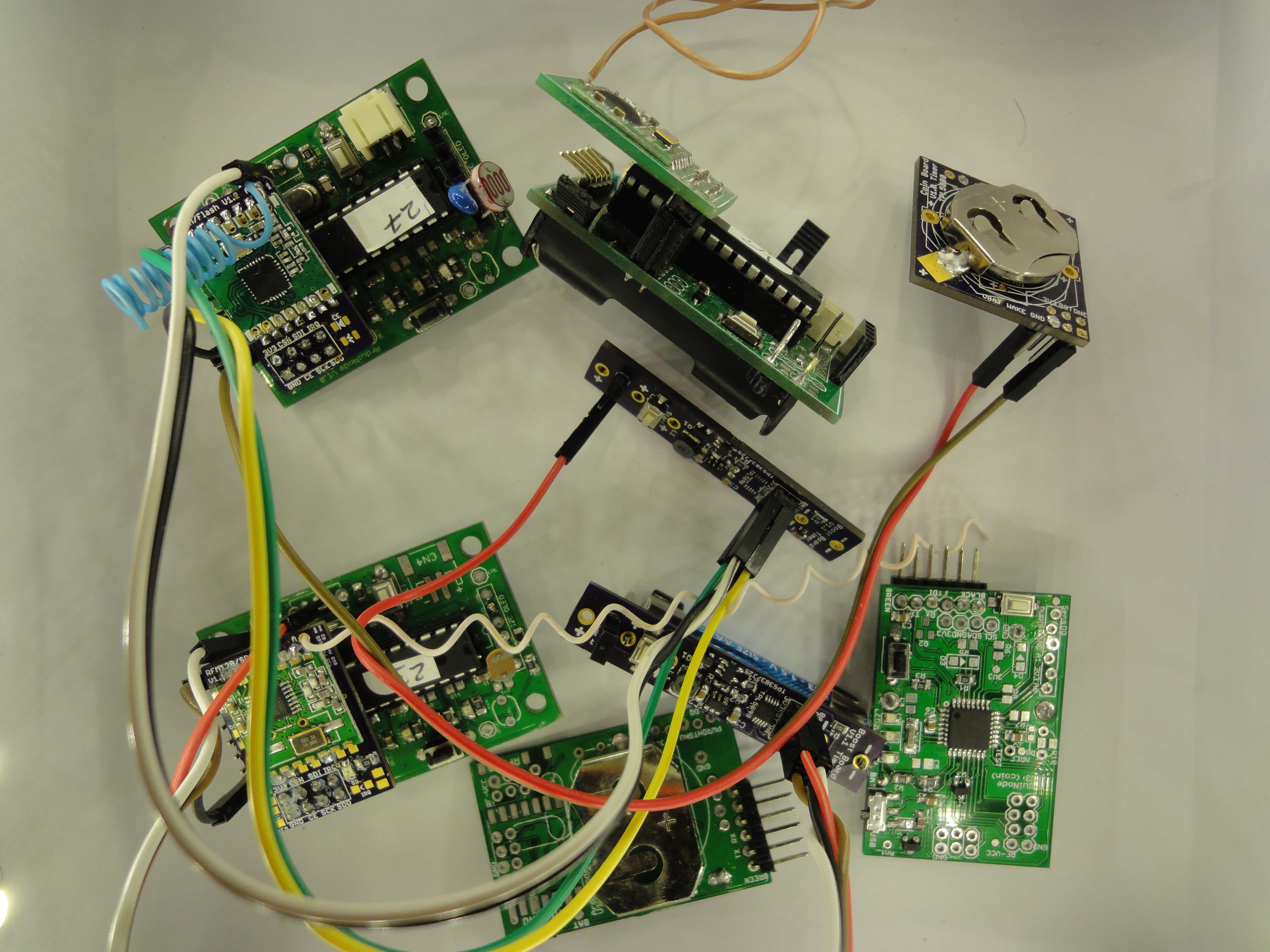
ULPNode Early Prototypes
I apologize for the time needed, but please be patient, writing is really time consuming and between, test, conception, headaches, hardware problems, software debugging, and my main full time job, remaining time is really really limited…
Stay tuned
Charles