Following the 1st part of bootloader description for ULPNode this article describe what modification have been done to optiboot to be able to drive new Ultra Low Power nodes.
Optiboot
For this, I started from original optiboot (latest trunk from google code) which is version 6.2 at the time of writing.
The process to build the bootloader is quite simple and the organization of the files are very well done so that we can implement customization without touching too much original files (except the optiboot.c source file of course). I created a ulpnode folder under the Arduino bootloaders setup folder (mine is located in Arduino-Install-Dir\hardware\arduino\bootloaders\ulpnode\) and put all necessary files into this folder.
New Makefile, new parameters
To be able to drive the new pins described in the previous article and to use same technique as LED done in the original bootloader I created a new include file with all the definition needed, this file is just a copy of original pin_defs.h that I called ulpnode.h and tweaked for the new pins. With this new file we’re now able to pass the pins parameters on the command line at build exactly the same way it has been done for others parameters such as
LED=B5 LED_START_FLASH=1 ....
The parameters are the following :
- WS2812=D6 Pin to drive WS2812 LED, PORTD6=D6 of Arduino
- WAKE_SWITCH=D4 input pin of the manual Wake switch, PORTD4=D4 of Arduino
- PWR_SENSOR=B1 output pin to power up the sensors, PORTB1=D9 of Arduino
- PWR_BOOST=C2 output pin to power up the sensors, PORTC2=A2 of Arduino
- PWR_RF=D7 output pin to power up the radio module, PORTD7=D7 of Arduino
Then I created a new makefile called Makefile.ulpnode containing the build process of the ULPNode bootloader. This is the new file (also on github) :
#
# Makefile for Ultra Low Power Node ULPNODE
#
# see hallard.me/ulp-bootloader for more information
#
# License : Attribution-ShareAlike CC BY-SA
#

#command line new parameters dedicated to ULPNode
ifdef WAKE_SWITCH
ULPNODE_CMD += -DWAKE_SWITCH=$(WAKE_SWITCH)
endif

ifdef PWR_BOOST
ULPNODE_CMD += -DPWR_BOOST=$(PWR_BOOST)
endif

ifdef PWR_SENSOR
ULPNODE_CMD += -DPWR_SENSOR=$(PWR_SENSOR)
endif

ifdef PWR_RF
ULPNODE_CMD += -DPWR_RF=$(PWR_RF)
endif

ifdef WS2812
ULPNODE_CMD += -DWS2812=$(WS2812)
endif

# Chip level targets
#
ulpnode: TARGET = atmega328
ulpnode: MCU_TARGET = atmega328p
ulpnode: CFLAGS += $(COMMON_OPTIONS) -DBIGBOOT -DULPNODE=1 $(ULPNODE_CMD)
ulpnode: AVR_FREQ ?= 16000000L

# bootloader will use 1Kb of flash space, we need to start at address 0x7c00
# also to avoid retaining and looking into .lst generated file to obtain address of exported function
# I've put a new section containing function table address, this one is located at 0x7ff0 to 0x7ffd
# this is located just before optiboot version
ulpnode: LDSECTIONS  = -Wl,--section-start=.text=0x7c00 -Wl,--section-start=.functable=0x7ff0 -Wl,--section-start=.version=0x7ffe

ulpnode: CFLAGS += $(UARTCMD)
ulpnode: ulpnode_$(BAUD_RATE)_$(AVR_FREQ)Hz.hex
ulpnode: ulpnode_$(BAUD_RATE)_$(AVR_FREQ)Hz.lst

# tricky part I spent time to find out why my new section .functable was not working
# we need to add it to this part
ulpnode: OBJCOPY += -j .functable --set-section-flags .functable=alloc,load

# this is for ISP, did not test, not sure this part is working.
ulpnode_isp: ulpnode
ulpnode_isp: TARGET = ulpnode
ulpnode_isp: MCU_TARGET = atmega328p
# 1024 byte boot, SPIEN
ulpnode_isp: HFUSE ?= DC
# Low power xtal (16MHz) 1KCK/14CK+0ms
ulpnode_isp: LFUSE ?= 6E
# 1.8V brownout
ulpnode_isp: EFUSE ?= FE
ulpnode_isp: isp
To be able to compile for ULPNode I needed to edit the original Makefile to include this one. It has a dedicated section for this and I just added the line include Makefile.ulpnode on the section as follow
#
# Include additional platforms
include Makefile.extras
include Makefile.1284
include Makefile.custom

#ulpnode build
include Makefile.ulpnode
New parameters, new batch file to build
Now a batch file ulpnode.bat for testing and launch the build process that contains the following
@ECHO OFF
REM let's compile for a real ULPNode target 4MHz 250000 kbps
SET AVR_FREQ="AVR_FREQ=4000000"
SET BAUD_RATE="BAUD_RATE=250000"

REM Arduino classic LED pin on ULPNode
SET LED=LED=D5

REM WS2812B Data In avr pin
SET WS2812="WS2812=D6"

REM Number of flash when entering bootloader
SET LED_START_FLASHES="LED_START_FLASHES=3"

REM Wake up switch avr pin
SET WAKE_SWITCH="WAKE_SWITCH=D4"

REM power sensor avr pin
SET PWR_SENSOR="PWR_SENSOR=B1"

REM power RF Radio module avr pin
SET PWR_RF="PWR_RF=D7"

REM booster enable avr pin
SET PWR_BOOST="PWR_BOOST=C2"

REM Compilation call for ULPNode
@ECHO ON
..\..\..\tools\avr\utils\bin\make OS=windows ENV=arduino %AVR_FREQ% %BAUD_RATE% %LED_START_FLASHES% %WS2812% %WAKE_SWITCH% %PWR_SENSOR% %PWR_BOOST% %PWR_RF% ulpnode %*
@ECHO OFF
Hummm, I can hear some readers asking what are these fancy frequency 4MHz and 250Kbps baud rate ?? Well the 4MHz frequency is explained in the 1st article (just because ULPNode is running at 4MHz to be able to run until 1.8V) but the 250Kbps isn’t.
Upload yes, but upload right
Ok, it’s time to explain. The serial speed port of Arduino is a derivative of frequency and depending on speed you want to achieve and crystal frequency it can introduce some shifting. And that is exactly why on original optiboot build process, this derivation (called %error) is checked to be sure you will be able to upload your sketch at the frequency you choose with the on board crystal. Here we’re running at 4MHz and it’s just impossible to get reliable 115 200 kbps default Uno baud rate working (see datasheet below). The error at 4MHz is just 8.5% and still -3.5% in best case at 8MHz
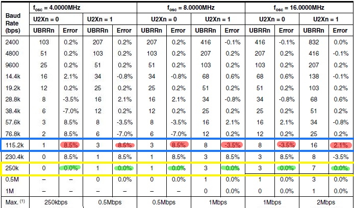
Atmega328P UART Speed settings vs Frequency
But looking closer at the datasheet you will find that at 250 000 kbps you always have 0% error. Amazing, since all USB/FTDI chips used to upload sketch are able to do this speed I’m still wondering why it’s not used. I have all my Arduino board flashed with 250 000 kbps uploading. The drawback is that Arduino IDE does not permit Serial monitor to work at this speed even if the serial port is capable of. You can always in your sketch use a
Serial.begin(115200);
configuration, but once again, at 4MHz this will not work, so using Arduino serial monitor should be setup with 38 400 kbps. If you want to serial monitor at 250 000 kbps, you will need to use other tool such as putty.
Of course you can stay on the well known speed, for 4MHz, but you will need to upload at 38 400 kbps. It works, uploading is just slower. I’ve tested a workaround, compiling bootloader for 16MHz and just before upload, set clock prescaler to 1 to use 16MHz speed, this is working fine, so why I did not used this technique ?
Because the WS2812B led driver is included onto the bootloader. This driver code is compiled for a specific speed (and it’s very time critical) and I wanted ULPNode able to light the LED when running at 4MHz (it normal speed) without the need to go to 16MHz speed just to light LED. And as the WS2812B driver code is shared between bootloader and sketch, when called, both need to be at 4MHz. I privileged ULPNode LED code instead of the bootloader one, but it’s just an arbitrary choice that you can change depending on your need.
What is changed on bootloading view ?
Beside including the WS2812B driver code (thank’s Tim) I included in the bootloader the Low Power management to boot without consuming unneeded power. Here the working flow of this new ulpnode bootloader
- Set PWR_RF I/O as output to disable powering RF Radio Module
- Set PWR_SENSOR I/O as output to disable powering sensors
- Set WAKE_SWITCH I/O as input/pull up for reading wake up switch
- Set PWR_BOOT I/O as output for driving DC booster
- Enable DC booster
- Check if FTDI module is connected or if Wake Up switch is pressed
- Set working speed to 4MHz (remember CLKDIV8 so 2MHz)
- If Wake Up switch is pressed or FTDI Module connected
- Go to bootloader for potential upload
- Flash led with color depending on Switch pressed or FTDI detected
- blah blah blah, … same as original
- If nothing to do, reset after 1S and start sketch
- Else
- Launch immediately user application (sketch)
This mean, that if no FTDI adapter is connected and the wake up switch is not pushed, the code start the sketch immediately running at 4MHz with the DC booster enabled. If not, the LED will flash (if defined so), bootloader will upload (if needed and found) and the sketch will start with DC booster Enabled
This order is subject to change depending on more testing. I need to test and tweak this with the real ULPNode boards. Of course for the example flashing the LED 3 times is not Low Power even if it’s not at full brightness.It’s fine for testing but for example you could blink 3 times when connected with FTDI powering the board, 1 time only when Wake Up switch is pressed, and no flash if none of the above is happening.
Compile ULPNode bootloader
The compilation is straight forward, just open a command line and go to the folder of ulpnode (mine is located in Arduino-Install-Dir\hardware\arduino\bootloaders\ulpnode\) and issue a ulpnode command. Here the result on my computer :
S:\Skydrive\PortableApps\Arduino-1.0.5\hardware\arduino\bootloaders\ulpnode>ulpnode.bat

S:\Skydrive\PortableApps\Arduino-1.0.5\hardware\arduino\bootloaders\ulpnode>..\..\..\tools\avr\utils\bin\make OS=windows
 ENV=arduino AVR_FREQ=4000000 BAUD_RATE=250000 LED=D5 LED_START_FLASHES=3 WS2812=D6 WAKE_SWITCH=D4 PWR_SENSOR=B1 PWR_BOO
ST=C2 PWR_RF=D7 ulpnode
avr-gcc (WinAVR 20081205) 4.3.2
Copyright (C) 2008 Free Software Foundation, Inc.
This is free software; see the source for copying conditions.  There is NO
warranty; not even for MERCHANTABILITY or FITNESS FOR A PARTICULAR PURPOSE.

BAUD RATE CHECK: Desired: 250000, Real: 250000, UBRRL = 1, Error=0.0%
../../../tools/avr/bin/avr-gcc -g -Wall -Os -fno-split-wide-types -mrelax -mmcu=atmega328p -DF_CPU=4000000  -DBAUD_RATE=
250000 -DLED_START_FLASHES=3    -DLED=D5  -DBIGBOOT -DULPNODE=1 -DWAKE_SWITCH=D4 -DPWR_BOOST=C2 -DPWR_SENSOR=B1 -DPWR_RF
=D7 -DWS2812=D6    -c -o optiboot.o optiboot.c
optiboot.c:381: warning: 'flash_led' declared 'static' but never defined
../../../tools/avr/bin/avr-gcc -g -Wall -Os -fno-split-wide-types -mrelax -mmcu=atmega328p -DF_CPU=4000000  -DBAUD_RATE=
250000 -DLED_START_FLASHES=3    -DLED=D5  -DBIGBOOT -DULPNODE=1 -DWAKE_SWITCH=D4 -DPWR_BOOST=C2 -DPWR_SENSOR=B1 -DPWR_RF
=D7 -DWS2812=D6  -Wl,--section-start=.text=0x7c00 -Wl,--section-start=.functable=0x7ff0 -Wl,--section-start=.version=0x7
ffe  -Wl,--relax -nostartfiles -nostdlib -o optiboot_ulpnode_250000_4000000Hz.elf optiboot.o -lc
../../../tools/avr/bin/avr-size optiboot_ulpnode_250000_4000000Hz.elf
   text    data     bss     dec     hex filename
    848       2       0     850     352 optiboot_ulpnode_250000_4000000Hz.elf
../../../tools/avr/bin/avr-objcopy -j .functable --set-section-flags .functable=alloc,load  -j .text -j .data -j .versio
n --set-section-flags .version=alloc,load -O ihex optiboot_ulpnode_250000_4000000Hz.elf optiboot_ulpnode_250000_4000000H
z.hex
..\..\..\tools\avr\bin\avr-objdump -h -S optiboot_ulpnode_250000_4000000Hz.elf > optiboot_ulpnode_250000_4000000Hz.lst
rm optiboot.o optiboot_ulpnode_250000_4000000Hz.elf
S:\Skydrive\PortableApps\Arduino-1.0.5\hardware\arduino\bootloaders\ulpnode>
You have now a file named
ulpnode_250000_4000000Hz.hex
in the current folder. For flashing this image, my recommendation is to use Atmel AVR studio. Dealing with fuses with avrdude requires speaking hex fuses language combined with bit action knowledge. I prefer using the GUI since I can see and set the option and also since I bricked some device dealing with avrdude bad fuses setting (ok it was not a avrdude problem, just the human using it). So since I’m using AVR Studio GUI, all is fine for me. The fuses setting for ULPNode should be as follow :
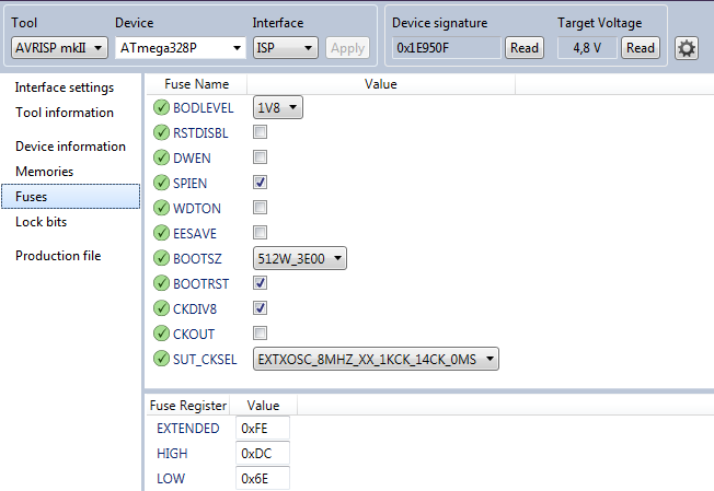
ULPNode Fuses settings
Once fuse are programmed flash the hex file and you’re done. Once again I’m using AVR Studio for this. If all went fine and have a FTDI connected to your board, you should see 3 purple flashes on the WS2812B LED as soon as flash is finished or if you reset your board.
Edit 02/19/2015
I faced some problems during testing when programing large sketch that were uploading data over the bootloader code and thus erased the bootloader code. This even if arduino IDE said that the code size was not “too big”. I opened a thread on Arduino forum about this issue.
The only way to get back was to burn bootloader again, but learning experience from this I looked into Lock settings and found a way to avoid bootloader write by application but keep application calling function into bootloader and able to read function table call from it. Here are the fuse to setup to achieve this
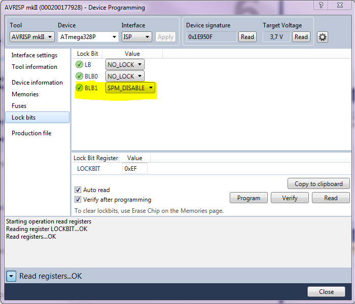
ULPNode Lock Fuses
End Of Edit
Upload sketch to ULPNode
If you have now your bootloader compiled and flashed, you should be able to upload sketch to ULPNode. If you kept the ULPNode default configuration and didn’t changed the frequency or baud rate, you certainly want to upload a sketch but remember that this board works at 4MHz with 250 000 kbps. No board of this type exist on the Arduino IDE, so we need to declare it. It’s quite simple just add the following section to the boards.txt file located into your Arduino Installation (mine is located in Arduino-Install-Dir\hardware\arduino\).
##############################################################

ULPNode4MHz.name=ULPNode 4MHz (250K upload)
ULPNode4MHz.upload.protocol=arduino
ULPNode4MHz.upload.maximum_size=31744
ULPNode4MHz.upload.speed=250000
ULPNode4MHz.bootloader.low_fuses=0x6e
ULPNode4MHz.bootloader.high_fuses=0xdc
ULPNode4MHz.bootloader.extended_fuses=0xfe
ULPNode4MHz.bootloader.path=ulpnode
ULPNode4MHz.bootloader.file=ulpnode_250000_4000000HZ.hex
ULPNode4MHz.bootloader.unlock_bits=0x3F
ULPNode4MHz.bootloader.lock_bits=0xEF
ULPNode4MHz.build.mcu=atmega328p
ULPNode4MHz.build.f_cpu=4000000L
ULPNode4MHz.build.core=arduino
ULPNode4MHz.build.variant=standard

##############################################################

ULPNode16MHz.name=ULPNode 16MHz (250K upload)
ULPNode16MHz.upload.protocol=arduino
ULPNode16MHz.upload.maximum_size=31744
ULPNode16MHz.upload.speed=250000
ULPNode16MHz.bootloader.low_fuses=0x6e
ULPNode16MHz.bootloader.high_fuses=0xdc
ULPNode16MHz.bootloader.extended_fuses=0xfe
ULPNode16MHz.bootloader.path=ulpnode
ULPNode16MHz.bootloader.file=ulpnode_250000_4000000HZ.hex
ULPNode16MHz.bootloader.unlock_bits=0x3F
ULPNode16MHz.bootloader.lock_bits=0xEF
ULPNode16MHz.build.mcu=atmega328p
ULPNode16MHz.build.f_cpu=16000000L
ULPNode16MHz.build.core=arduino
ULPNode16MHz.build.variant=standard
Then restart Arduino IDE, you just need to select the new board type
ULPNode 4MHz (250K upload)
and flash your sketch. Do not forget that at 4MHz you won’t be able to serial console at 115 200 kbps. Use 38 400 kbps from Arduino IDE (but upload still goes at 250 000 kbps).
I’ve also added a 16MHz version in case you want to use ULPNode as classic “Arduino” but with upload up to 250 kbps.
How declare bootloader function as exportable to sketch ?
To be able to call a function located into the bootloader section, we need to know the address of the function and do a call to this function. To obtain the function address, the basic and weird way is to take a look to the .lst file generated when compiled the bootloader, and, put this address in you sketch.
Here is an example, the function to light the WS2812B led is called
__bl_showLED
found in the generated .lst file.
void getNch(uint8_t count) {
    7eda:	1f 93       	push	r17
    7edc:	18 2f       	mov	r17, r24
  do getch(); while (--count);
    7ede:	e3 df       	rcall	.-58     	; 0x7ea6 <getch>
    7ee0:	11 50       	subi	r17, 0x01	; 1
    7ee2:	e9 f7       	brne	.-6      	; 0x7ede <getNch+0x4>
  verifySpace();
    7ee4:	f2 df       	rcall	.-28     	; 0x7eca <verifySpace>
}
    7ee6:	1f 91       	pop	r17
    7ee8:	08 95       	ret

00007eea <__bl_showLED>:

// Transmit a led color array to the WS2812B LED
// datlen is the lengh of the array, so it is equal to
// the number of LED * 3 (1 led = Red + Green + Blue values)
void  __bl_showLED(uint8_t *data, uint16_t datlen)
{
    7eea:	fc 01       	movw	r30, r24
  uint8_t curbyte,ctr,masklo,maskhi;
  uint8_t sreg_prev;

  // Set control pin as output
  LED_DDR |= _BV(LED);
    7eec:	56 9a       	sbi	0x0a, 6	; 10
You can see that the function address is identified at 0x7eea by the line
00007eea <__bl_showLED>:
. But this is not really convenient since each modification on the bootloader code could change this address and you will need to report back this change in your sketch code.
Any tip to avoid this ? Sure !, the idea is to put on the bootloader area a mapping table with the addresses of the functions to export. And set this area on a well know defined address. Here I choose to place this table just before the optiboot version number, at the end of the flash area.
The optiboot version number is two bytes located at the end of the flash area, at address 0x7ffe/0x7ffff. Our function table will be located on a new section starting at 0x7ff0 to 0x7ffd which let us to put 7 functions addresses (one address is two bytes). Adding a section for compiler and linker is an easy and convenient way to reserve this space.
Now let’s look closer to our Makefile.ulpnode file. The first interesting line for this is the following :
ulpnode: LDSECTIONS = -Wl,--section-start=.text=0x7c00 -Wl,--section-start=.functable=0x7ff0 -Wl,--section-start=.version=0x7ffe
I just added
-Wl,--section-start=.functable=0x7ff0
to define our section .functable.
Now, for this to be working I also needed to add the following file to the Makefile.ulpnode. If it was not done it was not working (but compiled fine). Don’t ask me why, I duplicated the job done by optiboot to the section .version, may be related to the linker to create and allocate this space. If someone knows, it would be nice to tell me what it really does.
ulpnode: OBJCOPY += -j .functable --set-section-flags .functable=alloc,load
That’s all for the build process of this new section. Now let’s be using this new section in optiboot.c file
To identify bootlader exported function I prefixed them with __bl_ which make them more speaking when used in code or just reading it. The function to call to drive WS2812B leds is called
__bl_showLED
and the prototype is as follow
// Transmit a led color array to the WS2812B LED
// datlen is the lengh of the array, so it is equal to
// the number of LED * 3 (1 led = Red + Green + Blue values)
void  __bl_showLED(uint8_t *data, uint16_t datlen)
To place the address of this function to the function table in section .functable this instruction has been added to optiboot.c, just putting the address of __bl_showLED into our section
// here are our exported function mapping table (stored in section .functable)
// It start at end of bootloader 0x7ff0 just before optiboot stored version (0x7ffe)
// this will create a function table list with fixed addresses
// so we do not need to get address from .lst file at each bootloader compilation
// Add other here if you create more (space for 7 functions total)

// 1st funct __bl_showLED
void * __attribute__((section(".functable"))) func1=&__bl_showLED; // address of __boot_showLED function
Imagine you created another exportable function with different prototyping, for example :
uint8_t __bl_dummyCall(uint16_t)
then the previous declaration would be
// 1st funct __bl_showLED
void * __attribute__((section(".functable"))) func1=&__bl_showLED; // address of __boot_showLED function
// 2nd funct __bl_dummyCall
void * __attribute__((section(".functable"))) func2=&__bl_dummyCall; // address of __boot_dummyCall function
As you can see, there is no function prototype defined in the .functable section, only the function address, the prototype will be defined in the sketch file.
But how to call the exported function from sketch ?
To call the bootloader function to light WS2812B onboard LED, we just need to declare the address of the function table, read the address of the function from the table and define the function prototype pointing to this address. For this, we use the macro
pgm_read_word
that I included in a more friendly macro called
__BL_FUNCTION_ADDRESS
with the number of the function we need to retrieve (1 for the 1st declared in optiboot.c and so on). Then we need to call the the macro
__BL_FUNCTION_ADDRESS(1)
to get the address of the 1st function located in bootloader table. Here it is what you’re sketch could look.
#include <avr/pgmspace.h>

// address of function table exported by the bootloader
#define __BL_FUNCTION_TABLE 0x7ff0

// return the address of function number (1..7)
#define __BL_FUNCTION_ADDRESS(fnum) (pgm_read_word(BOOTLOADER_FUNCTION_TABLE+((fnum-1)<<1)))

// declare a type of our function located into bootloader
typedef void (*__bl_showLED) (uint8_t *, uint16_t );

// now declare a function pointer to our declared function
__bl_showLED showLED;

void setup()
{
  // set address of the bootloader code to our 1st declared function pointer
  showLED = (__bl_showLED) __BL_FUNCTION_ADDRESS(1);

  Serial.begin(38400);
  Serial.println(F("Bootloader Call Test with WS2812B"));

  // Display the function address (should be 0x7ff0)
  Serial.print(F("__bl_showLED=0x"));
  Serial.println((uint16_t) showLED<<1,HEX);
}
Once this is done, you can call the function using the showLED function pointer as follow :
// Structure of the LED array
// depends on LED RGB or GRB, the one I have is GRB
struct cRGB { uint8_t g; uint8_t r; uint8_t b; };
//struct cRGB { uint8_t r; uint8_t g; uint8_t b; };

void loop()
{
  struct cRGB led;

  // Led Off
  led.r = 0 ; led.g = 0 ; led.b = 0 ;

  // call our function
  (*showLED)((uint8_t *)&led, sizeof(led));

  delay(500);

  // Led Purple, 1/2 luminosity
  led.r = 128 ; led.g = 0 ; led.b = 128 ;

  // call our function
  (*showLED)((uint8_t *)&led, sizeof(led));

  delay(500);
}
The above sketch will blink the WS2812B led in purple every second. You can see full sketch on github repo.
This is the end of this quite long article. I hope you found this article interesting. It’s the last concerning the bootloader stuff for ULPNode. It has been made for ULPNode but I think you can easily use it for any kind of Arduino board by tweaking the configuration parameters. It can be a good starting point.
You can find all files of this article on the dedicated ULPNode github repo
If you find any bugs, a better implementation or just add some features, just drop me a comment or better open a topic on the ULPNode forum.
Reference used
- Thank’s Tim for ws2812 avr library driver working on 4MHz devices
- Thank’s WestfW for original optiboot bootloader
- Optiboot wiki documentation
- Original optiboot working flow