I think there’s too much time I did not talked about ULPNode project, good news, it’s now time to talk about it and it’s timeline.
And it’s difficult to find a good starting point since all that I will describe is really linked.
- ULPNode hardware depends on ULPNode code library,
- ULPNode code library depends on
- ULPNode hardware, and gateway hardware
- RF Library Module (RFM69, NRF24L01, …) stack
- RF Protocol between gateway and ULPNode
- Gateway code and ULPNode code depends on RF protocol definition
- And one point is already covered and over, the Bootloader here and here.
Well looking at this seems complex, and it is, but if you just want to use it, all is already done and you just need to upload sample example code and you’re in, but I need to organize the way I will describe all of this. Let’s start!
Hardware
You will find below the boards I used to write all code going around this project. These board are named V1.2 but even if they are close to final design it will not the be the case. I will describe why below, but for now, it’s time to picture prototype boards 😉
ULPNode Top View
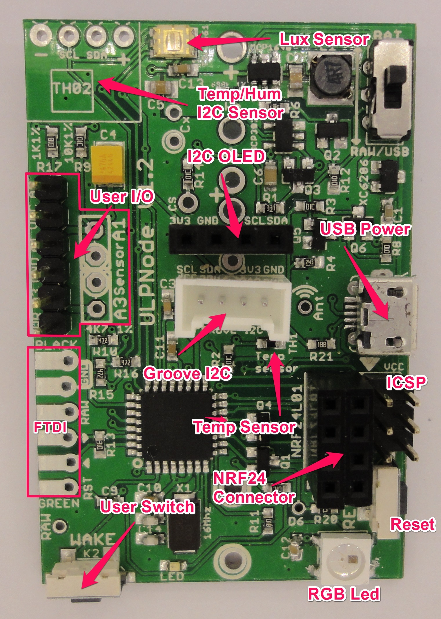
ULPNode Board, Top View
The board will include:
- NTC 10K 1% resistor to measure temperature
- 3 Analog pins (can work digital also) A0, A1, A3 each with different precision pullup resistor (1%) to be able to choose the correct one depending on sensors you want to add (if any)
- TSL2561 I2C Luminosity sensor (this one rocks!)
- User and reset Switch
- RGB LED
- On board LED
- Holes to connect various battery connectors (AA, AAA, CR3032, CR2450, CR123)
- Manual Start switch (may be needed to start booster)
- FTDI Connector
- Micro USB connector to power node if needed. V-USB component on board to be able to program using USB (but increase bootloader size and reduce flash size by 2KB)
- I2C Grove connector
- I2C OLED connector (don’t expect doing Ultra Low Power if you use one)
- NRF24L01 classic connector
- FTDI classic connector
Footprint for optional components:
- RFM69C/RFM12B module
- SI7021/HTU21D Temperature/Humidity sensor
- ATSHA204A on board for SHA256 key exchange (to be tested)
- 64kb SPI flash (need to be tested)
ULPNode Bottom View

ULPNode Board, Bottom View
ULPNode Filled with AA battery
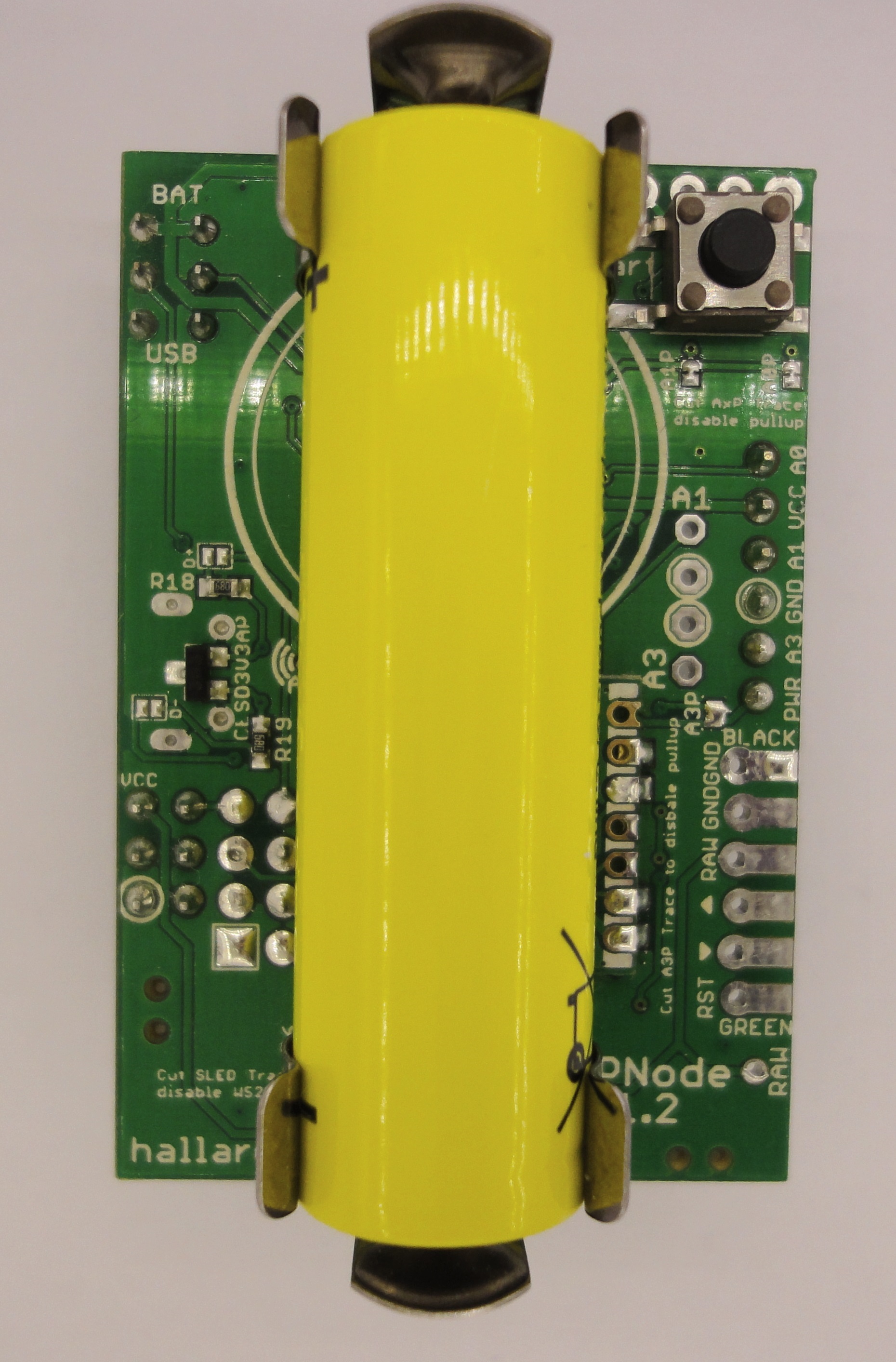
ULPNode Board, Bottom View with filled AA battery
Why a change in the design ?
1)
I discovered that the optional Temperature/Humidy sensor I made available to put on ULPNode board (top left), named TH02 does not work if there are any other I2C devices talking on the same I2C bus. Whoo, they claim I2C devices but it’s not the case.
For this reason I needed to switch to another device. I use the well known SI7021 so I will made PCB footprint for those who want’s to have it on next revision of ULPNode board. And thanks to my onboard I2C grove connector, I was able to test it without redesigning ULPNode board but just to use a custom grove I2C SI7021 Temperature Humidity board

Grove SI7021 Temperature/Humidity board
You can find information on how to build this grove board on my dedicated github
2)
Second reason is for hardware change, I need to arrange some components placement.
3)
This one is the last but not the least, I think I will totally change the board format to fit into a enclosure. I’m not sure for now this final decision. But finding a good enclosure is not so simple. I used the following one for other project and I already have eagle footprint so it’s just a matter of routing job on ULPnode board.

See more info on this one on manufacturer site.
By the way, even with board with enclosure size, you could leave as is also (ie no enclosure). So I need your help, I’m opening a vote on the community forum to determine how future ULPNode board will be.
You just need to follow the procedure in this post, if you already have an account with social authentication on the community forum, it will take less than 15 seconds.
Software
Playing now for months with some ULPNode testing board hardware revision V1.2 described above, I’ve been working last month intensively on testings and library coding.
The ULPNode code stuff is divided into 3 parts as follow :
- ULPNode RF Protocol
- ULPNode Library
- ULPNode Gateway
ULPNode RF Protocol
ULPNode RF protocol is the common code to link between Gateway and Node, mainly payload definition and protocol frame decoding. full description is already available on this dedicated blog post and sources code are already released on github.
ULPNode library
The library for ULPNode Arduino boards, I tried several ideas but my main concern when coding ULPNode Library was
- Ultra Low Power optimized code
- Painless use
- Trying to not be other lib depends on other libs (only RadioHead)
- Usable on any board type with minor changes
- Well documented
- Heavily commented code
- Lots of examples and more
ULPNode Gateway
Code for any universal Gateway, for example Particle hardware but it could be ESP8266, Pi, Arduino, or even a ULPNode device itself.
The main concern about the gateway is the sketch size, on Arduino, with RF module Serial configuration, Debug, JSON output and OLED display I’m reaching the end of the flash size and adding new features such as DHCP management or OTA config will be very difficult (except removing OLED), and connecting Gateway to Internet require another device (Raspberry, NAS, computer, ..)
So a new simple target with plenty of RAM/Flash and WiFi connection such ESP8266 or Particle can also be great and remove the need of a Internet connected device.
Protocol between Gateway and world
The Gateway protocol for now is just returning JSON string over serial, and I push them to emoncms for testing using node red on a raspberry PI (see below)
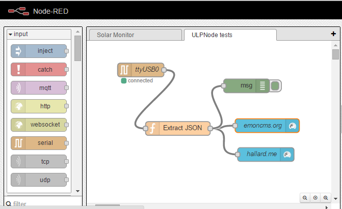
ULPNode Raspberry PI with Node RED sending to emoncms
But it will be simple to comply to any existing ptotocol and I will make it compatible with MySensors Serial API protocol
Bonus : 2 gateways pictures running, the 1st one with a Moteino and 1.3″ OLED display

ULPNode Gateway With Moteino
The next one is more funny. It’s an ULPNode itself, powered by a single AA battery, not sure how long it can go on this since gateway has no code for Low Power, but it should be possible to sleep gateway and wake it up on message reception.
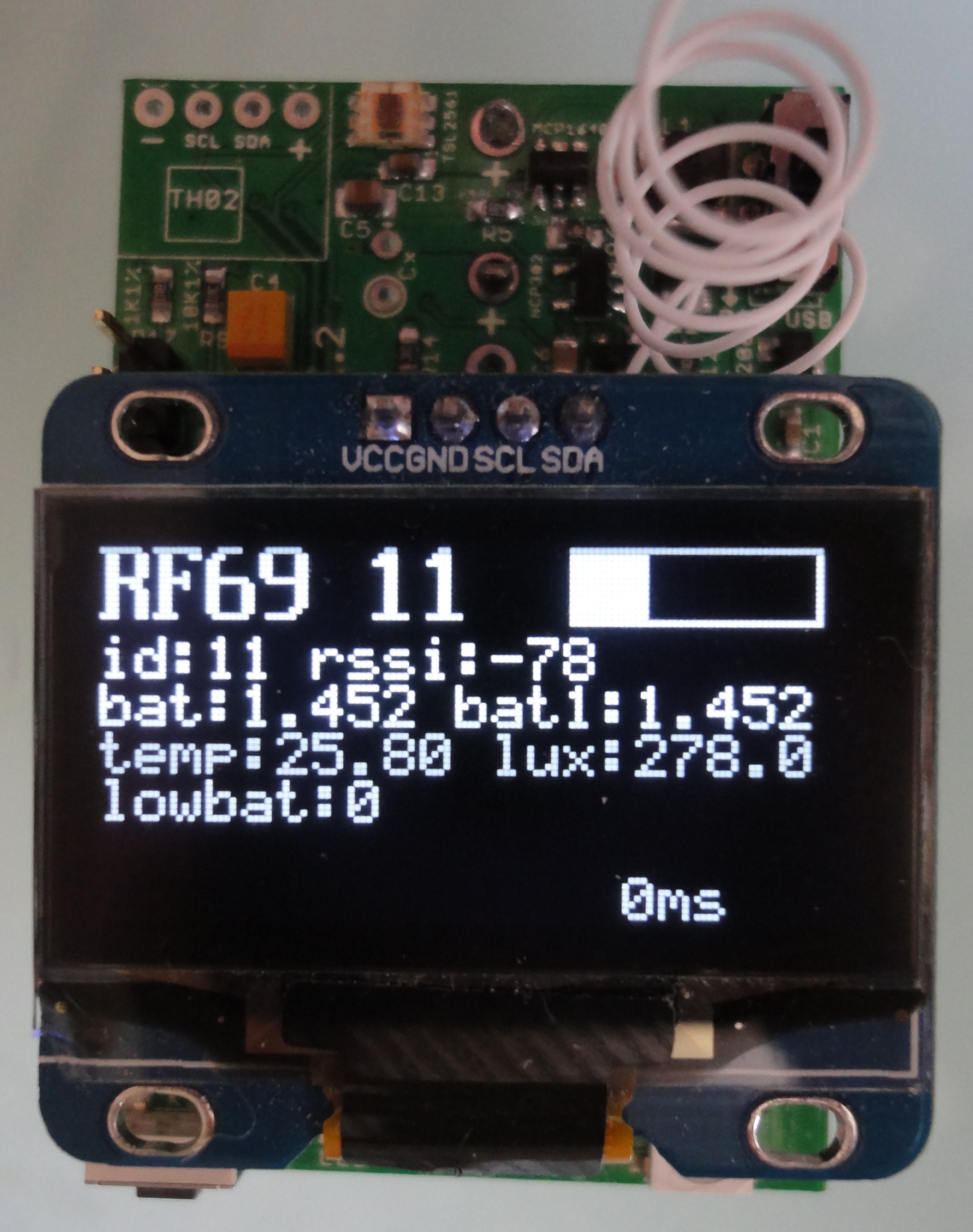
ULPNode Gateway With another ULPNode powered by a single AA battery
Hey, I’m thinking, it should be possible to do a simple battery checker with display with this board just by changing code. Just to clip the battery to test, and if it work, display battery voltage, if not the battery is really down because the one I used for this example picture was around 1.1V, so really low and it worked, amazing !!!!
Next steps
ULPNode library and Gateway code will be released in the next few days, links on this page and ULPNode community dedicated section will be updated according to. If you’re interested, I strongly recommend to follow (watch button once logged) the dedicated section on community forum to be notified on each new article.
Then I will do some change on PCB according the PCB version choice you prefer (you’re encouraged to vote here) and let them going to manufacture.
References
- ULPNode RF Protocol sources code
- ULPNode section on the community forum
- All ULPNode related articles on my blog
- Github repository
Stay tuned!
Charles