
MAX31865 board
Today I would like to introduce a new breakout board to read temperature values from the most used sensors in the industry such as PT100 and PT1000 (well at least in France).
Why this board ?
It’s not the first time I want to measure sensors but one of the most used in industry are the PT100 and PT1000, and a friend of mine asked me several times to be able to easily measure temperature with these sensors.
Conception
I wanted this board to be small and efficient and the ability to measure all PT100 ot PT1000 sensors, the one with 2, 3 or 4 wires. So I added several on board jumper pad to select the different mode.
I wanted also to use an existing pinout, so I choosed the well known NRF24L01 one. Which is really (almost I think so) the most used on sensors boards. The connector is present on my boards design such as ArduiPi and ULPNode boards. But you can also find it on several Arduino boards, even if pining may be different.
Target
You can use this breakout board with any embedded card such as Arduino (or ESP8266, Spark Core, Photon, OAK, …) . You just need to do some wiring if the NRF24L01 connector is not on the board. But it’s just 8 wires, it should be straightforward with some dupont cable.
Board pictures
Here another picture of the final board, you can zoom in clicking on the picture.
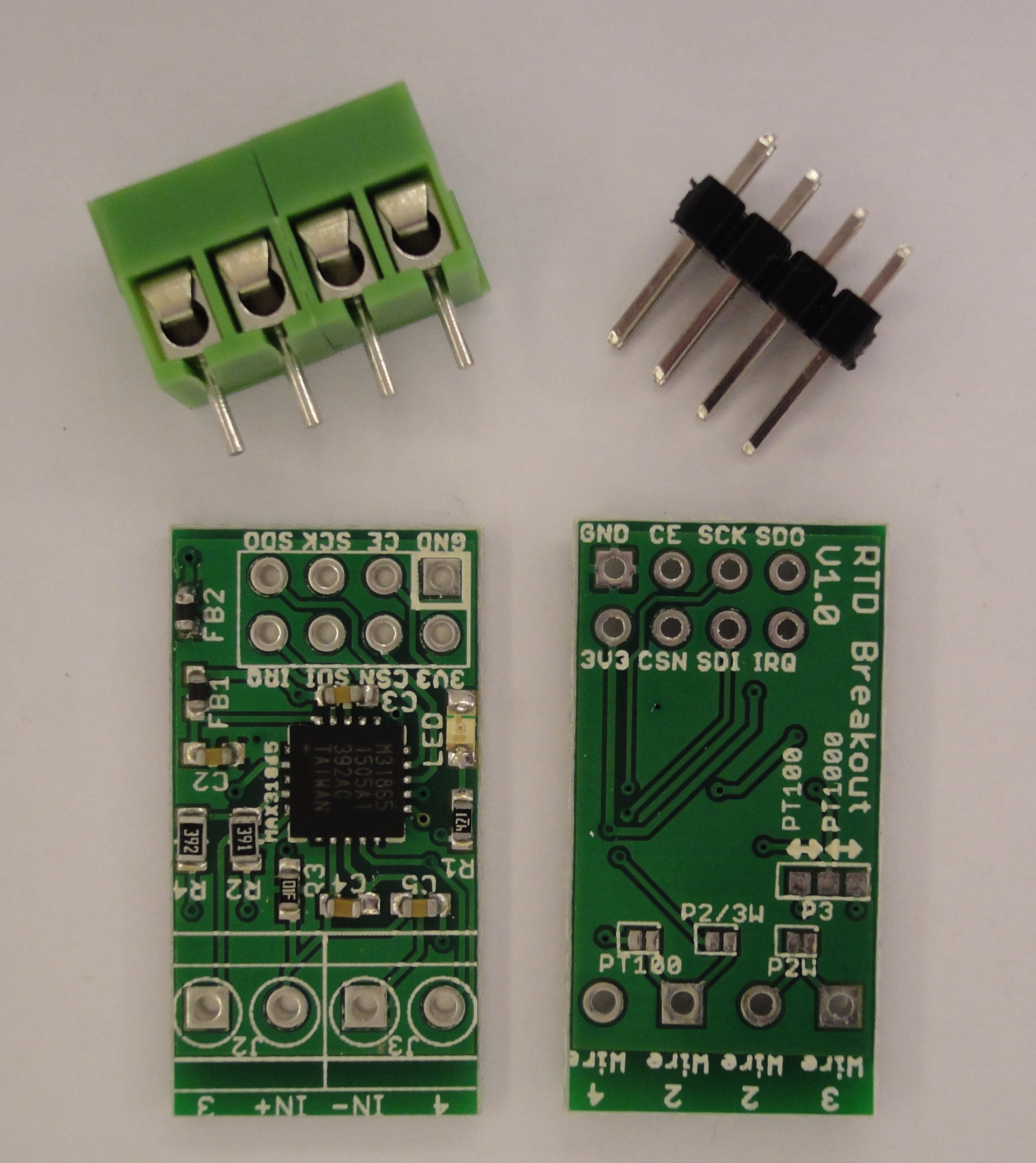
MAX31865 breakout board
Getting started
Following can be called a getting started section, I will describe how the board is made and how to use it. First of all let’s start by the board schematic
Schematic
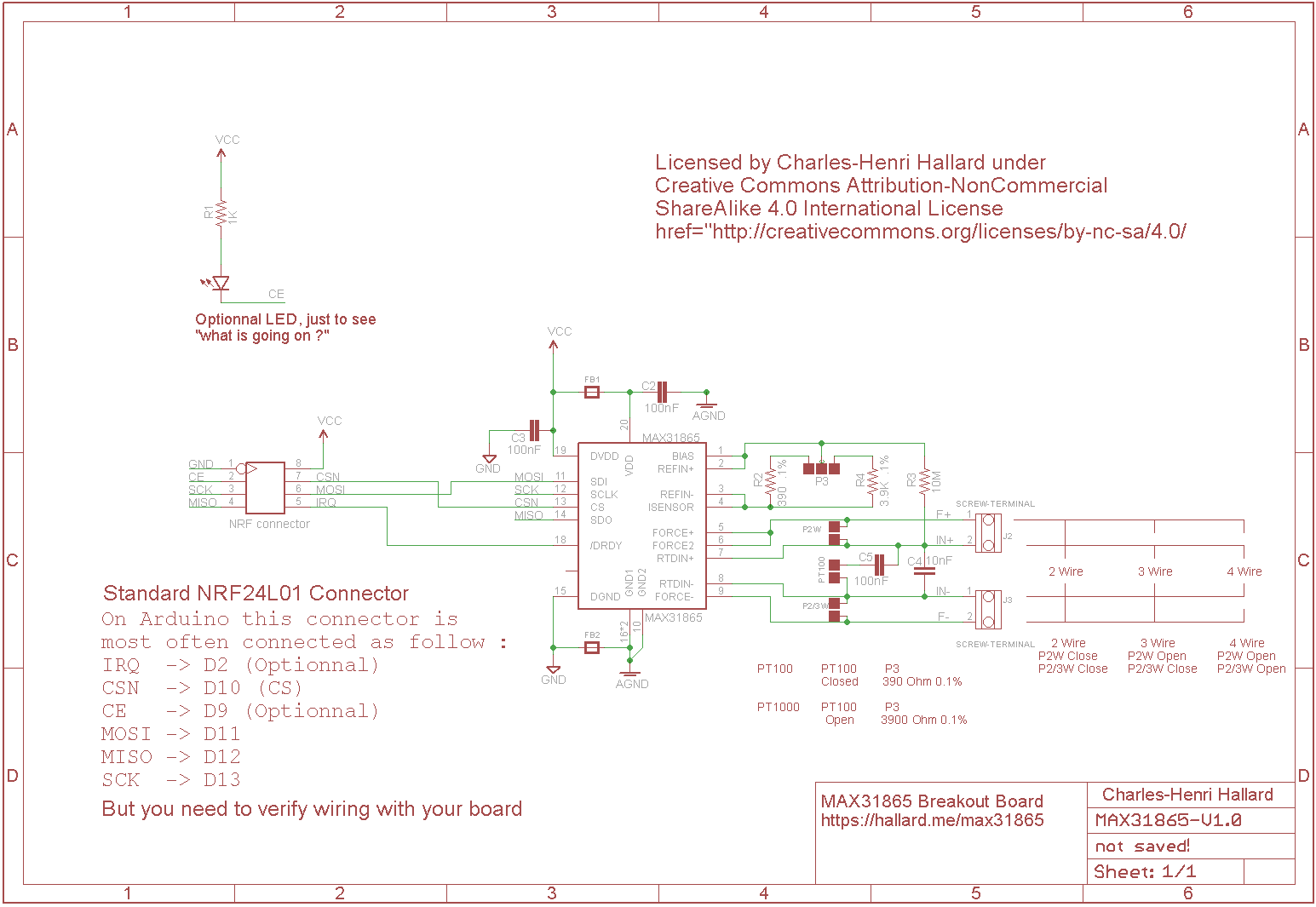
MAX31865 breakout board schematic
Nothing fancy, this design is very close from the original Maxim MAX31865 datasheet. Features are following :
- 2 references resistors (390 Ohms 0.1% and 3.9 KOhms 0.1%) and solder pad option to be able to select if you want to use the board with a PT100 or PT1000
- Can be used with 2, 3 or 4 wires PT100 or PT1000 (solder pad option)
- Filtered and separated Digital and Analog signals (ground/3.3V) using ferrite board
- On board led driven by target IO
- Ready signal (DRDY) connected to a target IO pin if needed
Connections
Let get a look to the NRF24L01 connector. Picture below is the top view.
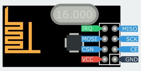
NRF24L01 Pinout top
And now the MAX31865 breakout board, pretty the same.
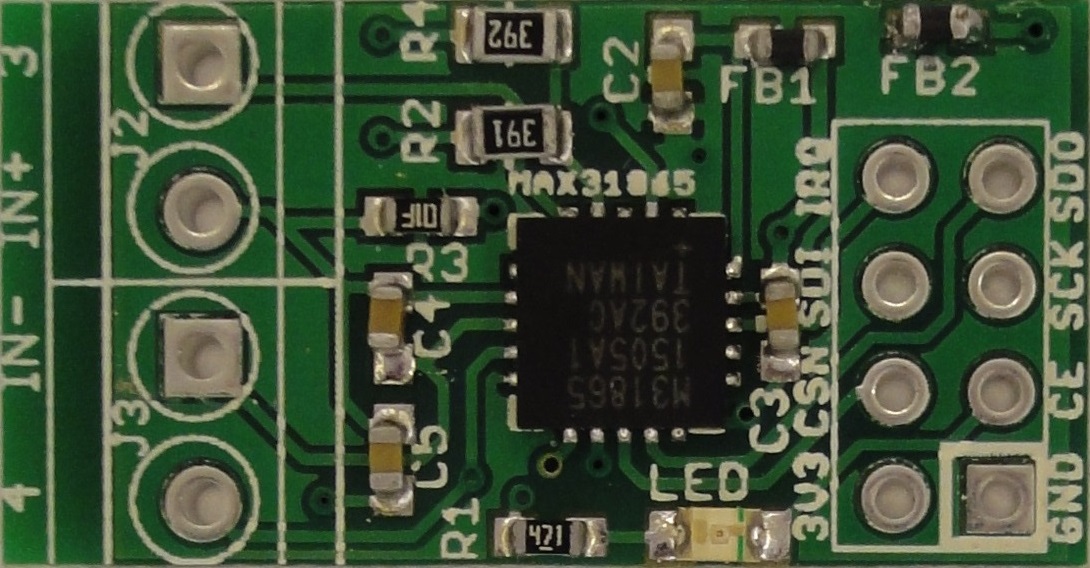
MAX31865 breakout board pinout
So there are 8 pins, described as follow and this is the same pinout for the MAX31865 breakout board divided into 3 groups. in parenthesis I indicated the Arduino pin where it’s generally connected to.
- Power
- GND connected to ground
- VCC/3V3 connected to 3.3V, do not connect it to 5V !!
Pay attention to board power, all the signals target board needs to run at 3.3V, connecting only VCC of the breakout to 3.3V is not enough if your Arduino board is running at 5V because SPI bus signal (SCK, MOSI and CSN) will get to 5V and dammage the breakout
- SPI Bus
- SCK clock (D13) 3.3V
- MISO/SDO serial data output from the module (D12)
- MOSI/SDI serial data input to the module (D11)
- CSN SPI chip select to indicate we want to speak to the module (D10)
- Others
- IRQ is the DRDY signal output from MAX31865 (D2)
- CE bonus pin, active LOW the onboard breakout LED (D8)
If you want the demo sketches do works, you need to connect the pin according to the definition above.
Set board configuration and connect sensor
Mainly you can have 2 values type of sensor, PT100 and PT1000 and for each 3 connections type, which are 2,3 or 4 wires.
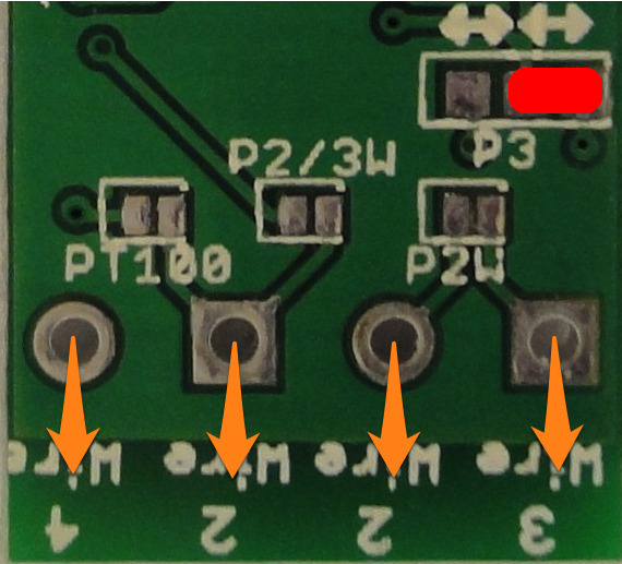
Before the first use, you need to put some solder on the pad to select which type of sensor you want to connect on. Here are the different options that are present on the bottom of the board. You will find in the picture below how to setup the board.
- The RED bullets represent on which pad you need to put solder to setup the configuration.
- The Orange where you need to connect the sensors wires. Of course if you use terminal block and if they are soldered on board, you just need to put the wires into and fix them with the screw.
For PT100 sensors (100 Ohms at 0°C)
PT100 : 2 Wires wiring
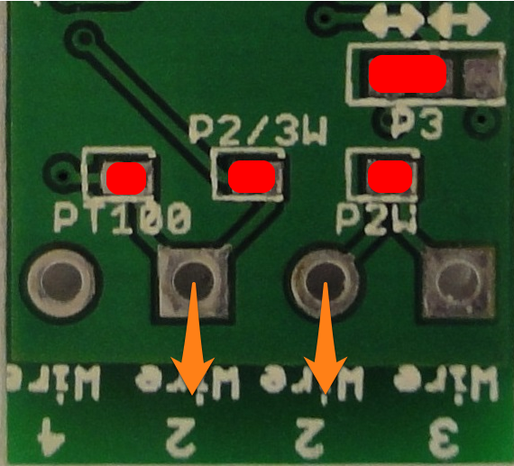
PT100 2 Wires
PT100 : 3 Wires wiring
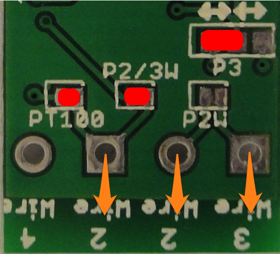
PT100 3 Wires
PT100 : 4 Wire wiring
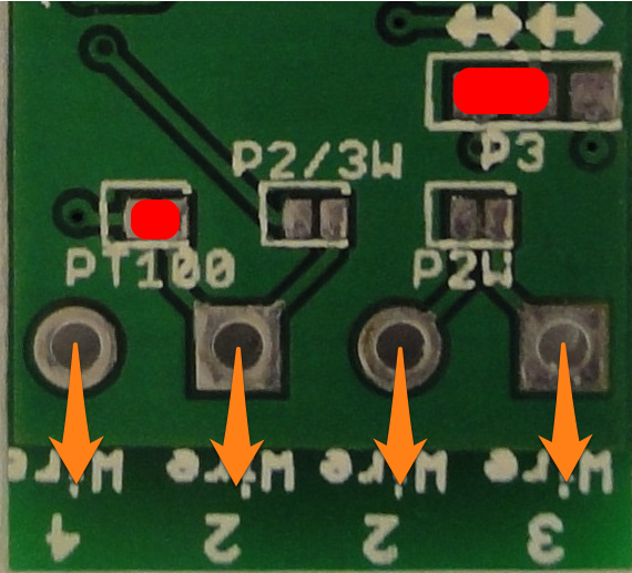
PT100 4 Wires
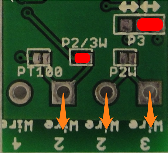
For PT1000 sensors (1000 Ohms at 0°C)
PT1000 : 2 Wires wiring

PT1000 2 Wires
PT1000 : 3 Wires wiring
PT1000 3 Wires
PT1000 : 4 Wires wiring
PT1000 4 Wires
Testing
Once the configuration has been setup as follow :
- Wiring to breakout board to Arduino (take care 3.3V Only)
- Put solder on pad
- Wired the sensor to the breakout board
You will need the modified MAX31865 Arduino library to be able to test the board. The library can be found on my github here. If you want to connect an optional OLED display you will also need the u8glib library.
You can now upload the sample sketch named Full_Test_Serial.ino or Full_Test_Oled.ino if you connected an I2C Oled on you board and let your serial monitor to 115200kbps.
Theses two sketches are setup for PT1000 2 wires, is you want to use PT100 you need to change the following definition
// define here PT1000 or PT100
// ===========================
#define PT1000
//#define PT100
to
// define here PT1000 or PT100
// ===========================
//#define PT1000
#define PT100
If you use 3 or 4 wires sensors, you also need to change following lines at the same place
// define here false for 2 wires
// true for 3/4 wires
// ==============================
#define USE_3WIRES false
//#define USE_3WIRES true
to
// define here false for 2 wires
// true for 3/4 wires
// ==============================
//#define USE_3WIRES false
#define USE_3WIRES true
And here the full serial output,
- first with all connected then
- disconnected the sensor
- disconnected the breakout board
Full_Test_Serial.ino
Jul 16 2015 17:10:10

2	Checking MAX31865 SPI chip...Found OK!
	  Checking manual fault detection Stage 1 status=00 => OK!
	  Checking manual fault detection Stage 2 status=00 => OK!
	  Starting conversion...(in 62ms) Status:00
	  RTD:9255 Ohms => Temp:26.1 C
	Done!

4	Checking MAX31865 SPI chip...Found OK!
	  Checking manual fault detection Stage 1 status=00 => OK!
	  Checking manual fault detection Stage 2 status=00 => OK!
	  Starting conversion...(in 62ms) Status:00
	  RTD:9256 Ohms => Temp:26.1 C
	Done!


22	Checking MAX31865 SPI chip...Found OK!
	  Checking manual fault detection Stage 1 status=20 => OK!
	  Checking manual fault detection Stage 2 status=08 => RTDIN- < 0.85x V_BIAS F- Open
	Done!

24	Checking MAX31865 SPI chip...Found OK!
	  Checking manual fault detection Stage 1 status=20 => OK!
	  Checking manual fault detection Stage 2 status=08 => RTDIN- < 0.85x V_BIAS F- Open
	Done!

38	Checking MAX31865 SPI chip...No communication, is breakout board plugged ?
	Done!

40	Checking MAX31865 SPI chip...No communication, is breakout board plugged ?
As you can see tests are done in real time and seems to work perfectly, look at below, display is working fine also 😉
Some pictures with OLED display

OLED With working breakout board
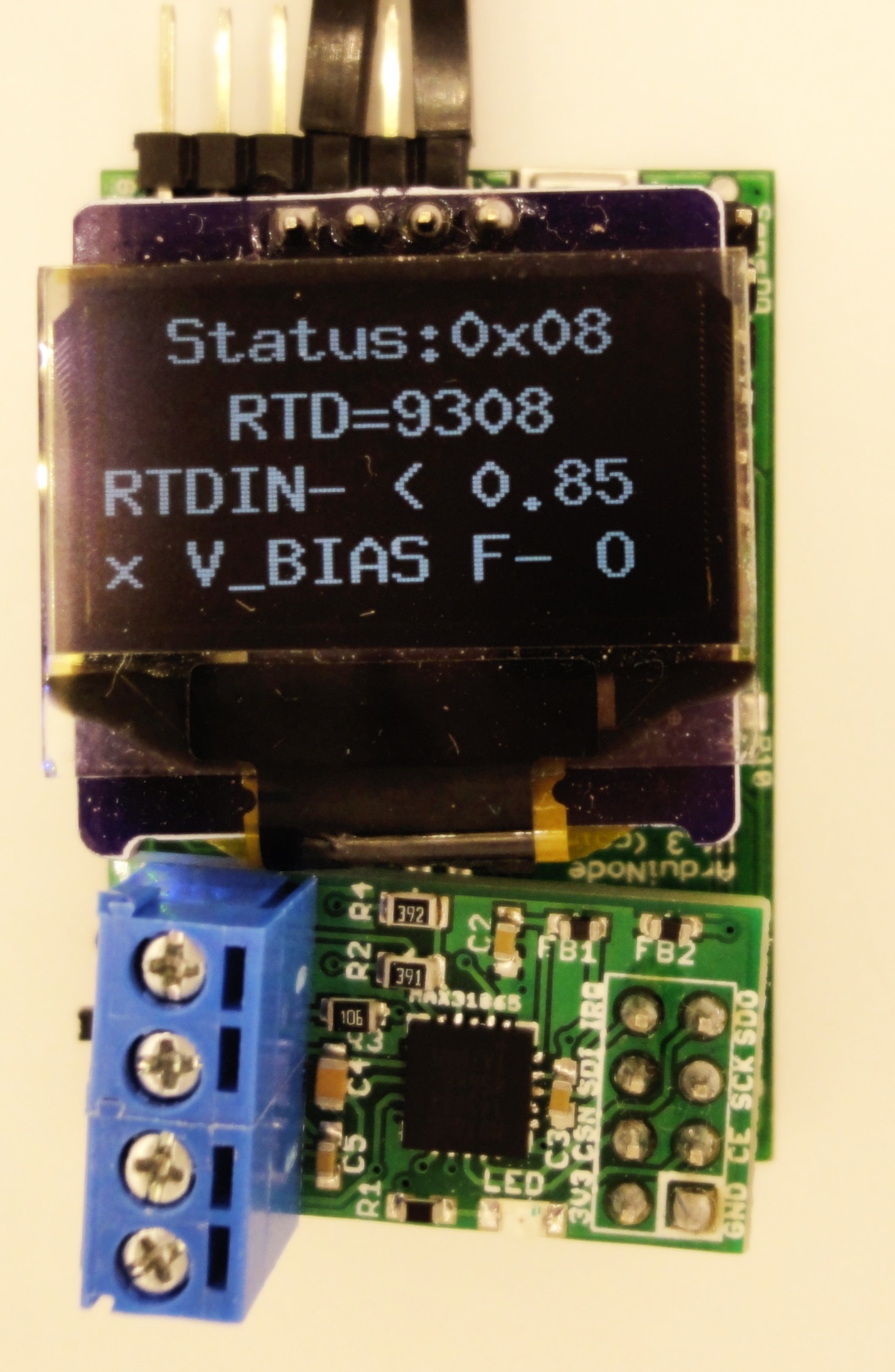
OLED With no sensor on breakout board
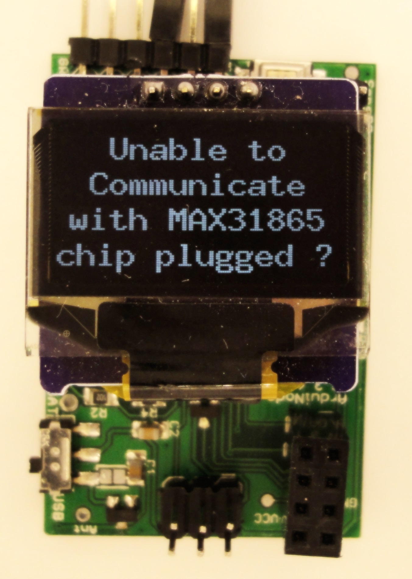
OLED With no breakout board
Want to get this breakout board ?
For those who wants to buy the already made board, you can do it on my tindie shop
Mes produits sont également disponibles sur Lectronz. Les clients européens peuvent préférer cette boutique qui propose des moyens de paiement supplémentaires et des prix en euros.


References
- MAX31865 Datasheet
- Schematics, Boards files in eagle cad format
- MAX31865 Library code
- Github link where all this project file are hosted
- buy the breakout board