Today I solved one of my “Auto-reset” like problem for ESP8266 which had some erratic comportment depending on ESP module used. Sometimes it was working all time and some other never. Investigation was planned, I really don’t had time for this but I like to understand what’s going on, and why ! I also wanted to share this with you so will be able to discuss on it.
I’m already hearing people saying, “why getting worried with this since now OTA (Wifi update) is working” ? Correct, but having classic FTDI serial connection can sometimes get you out of troubles, you need it one day or another in case of problem and also for the 1st flash time setting.
History
When I created the original WifInfo board, I’ve done it on a breadboard before creating the PCB design. I wanted to use an “auto-reset” feature as on Arduino to avoid playing with button on each upload. If it’s simple on Arduino because you just need to manage reset pin, on ESP8266 it’s more tricky because you need to have GPIO0 pin low when reseting the board to be able to upload firmware. That is why on some boards you have 2 push button for this.
Getting information through the Web, it came that a usual method used by NodeMCU for example was to use 2 transistors and 2 resistors coupled with an USB/Serial chip. Each transistor is connected to one pin of the USB serial converter. One for RTS the other for DTR as follow.
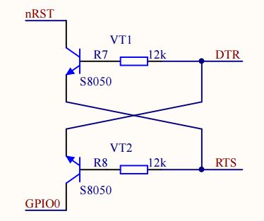
NodeMCU Autoreset
Of course with nRST and GPIO have pullup to VCC (12K). there are also some other schematics that I don’t describe here.
WifInfo board
But in my design case, I don’t want to have USB Serial converter (for price, size and soldering) on my board and I’m using classic FTDI modules with only DTR line and no RTS. So I started with schematic from excellent Adafruit Huzzah that I improved for Auto Reset.
Auto Reset
Based on Arduino trick to release reset pin with a 100nF capacitor, I implemented this one on my first design. Then wired DTR to GPIO0 to let it low while releasing reset. The schematic was the following one :
ESP8266 Auto Reset First Try
Check this !
Then I tried this idea on a breadboard as follow :

WifInfo Breadboard
and guess what ? worked flawlessly first time, I was happy since analog electronic is not really my best knowledge. I then captured Reset and GPIO0 signals to check. Here are the capture from the scope, Yellow is Reset and blue GPIO0
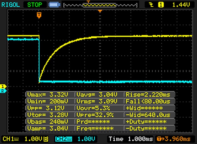
WifInfo Auto Reset
As you can see Reset line (yellow) is released and GPIO0 still set to low (blue) , fine ;-). Of course upload start and success.
Final design
It was time to design final board, I’ve done this on Eagle Cad and all building files are located on the WifInfo github repo.
When final boards arrived, I mounted some and started testing, here how board look like :

WifInfo Board
Even if boards were working fine, I wasn’t able to do any auto reset. I’ve checked and checked again to see were I’ve made a mistake, maybe on routing ?
But after investigation on PCB, problem was not on routing. I checked again on the breadboard and it was still working fine. So it was time to do further investigation
Get out the Rigol scope and dedicated testing board
I tried to capture the signal like I’ve done on the breadboard, but the Rigol was not triggering the signal except when I pushed on Reset button. The only difference with breadboard prototype and final board is the ESP8266 modules soldered on WifInfo. I tried WifInfo boards with ESP12 and ESP07 same things, no auto reset !
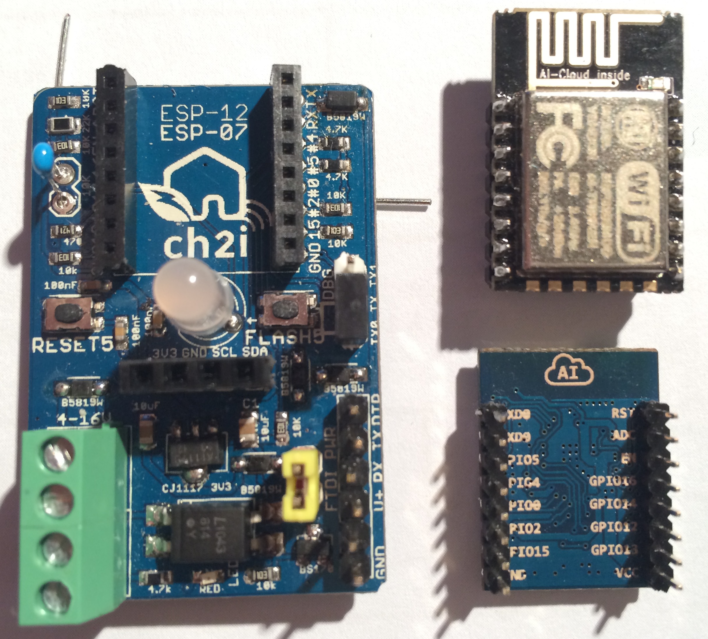
But on the Breadboard, the module is the blue ESP12 located on the right below, all other WifInfo boards have one of the 3 left modules, two ESP12 and one ESP07.

different WifInfo Modules
So I’ve done a board with 0.1″ female headers instead of soldering ESP module on it, and soldered some 1.27″ male headers on different modules. this gave me something like that (look at 2 old resistors pins used below the board to get Reset and GPIO0 signals connected to the scope :
WifInfo with ESP8266 headers
Then I tried to track reset line on WifTnfo board without any ESP module connected. And then the Rigol scope triggered on Low Reset line
WifInfo Auto Reset
Humm, all is fine, so I plugged ESP07 and tried again, oupss not triggered ? Ok, then I put the blue ESP12 Reset is triggered (as on the breadboard), that makes sense since it’s the same module used !!!
Problem identified : Internal ESP module Reset line
This clearly indicate that the problem is coming the way Reset line is connected inside the ESPxx Module. So I decided to take some measures on ESP modules between VCC pin and Reset pin to check pull-up resistor value .
The 3 modules on the left measures says 12K, this mean internally, reset line is pulled High with 12K resistor, good to know, this mean we don’t no need pullup on WifInfo board! Then I used the blue ESP12 (right one) and my Metrix told me 8M, that’s the difference between the modules (may be not the only one) and now makes senses and I’ve got better understanding of what is going on.
I also tried to remove my own pull-up (10K) on reset line to avoid paralleling 12K+10K just in case but it didn’t changed anything (as suspected). Reset line was not pulled low with FTDI. So I decided to search for something else.
Google around on reset function
So after I googled around to see what others are doing with Reset (here, here telling to connect DTR to CH_PD and here), I found interesting point. It seems that module Reset can be done with CH_PD line (pulling it low) leaving Reset alone with pull-up. And leaving Reset alone seems to be better for sleep/wake up mode (when GPIO16 connected to Reset) and avoid some problems in this case.
I decided to give a try. Since my CH_PD has a 10K pull-up resistor I just cut PCB wiring going to reset line of ESP module (before Reset pull-up of course) and connected to CH_PD, and tadaaaaaa…
It works now with every module. I’ve now got fully and working auto-reset with classic FTDI module having only one line : DTR 😉
I don’t know what some boards/bootloader make with reset line but my advice would be to let it alone and just use it when you ween wake up from sleep mode. And use CH_PD to reset your boards. If someone could give me more precise answer on this, I will update this post according to for others. I’m always interested to know how things are working.
Final Design
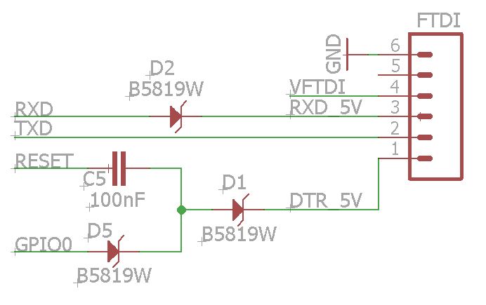
Anyway, here is the final schematic for auto-reset with FTDI module, it works in all case with my different modules. You can use either 3V3 or 5V FTDI modules, but with 3V3 you may need to power ESP with another source since 3V3 FTDI modules are not all able to source sufficient current, don’t forget this point!
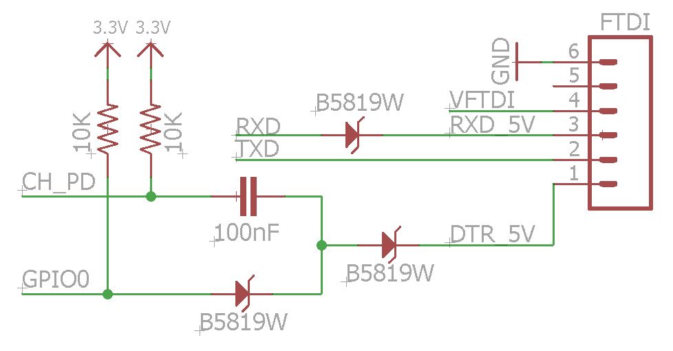
FTDI ESP8266 Auto Reset